


3 - 18
C156-E097-01EN
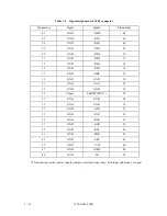
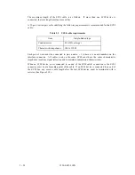
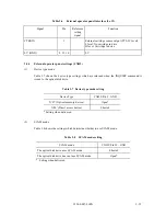
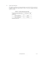
Table 3.4
Recommended components for connection
Category
Name
Model
Manufacturer
Symbol in Figure
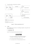
3.19
SCSI cable
Cable socket
(closed-end type)
FCN-707B050-AU/B
Fujitsu Ltd.
S01
Cable socket
(through-end type)
FCN-707B050-AU/O
Fujitsu Ltd.
Signal cable
UL20184-
LT25PX28AWG
Hitachi Cable, Ltd.
—
455-248-50
SPECTRA-STRIP
Power supply cable
Housing for cable
socket
1-480424-0
AMP
S2
Contact
170121-4
AMP
Cable
AWG18
—
—
External operator panel
Housing for cable
socket
LPC-16F02
Honda-Tsushin
SH2
Receptacle
LPC-F104N
Honda-Tsushin
Cable
AWG28
—
—
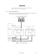
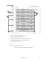
(1)
SCSI cable
All SCSI devices on one bus are daisy-chained with an SCSI cable. A terminating resistor must
be mounted in the SCSI device at each end of the SCSI cable.
A terminating resistor is mounted on the drive when the drive is shipped. A terminating resistor
must be disconnected when the drive is not connected to an end of the SCSI cable. Select a
method of power supply to the terminating resistor circuit according to the setting pins on the
drive. See Section 4.3 for details.
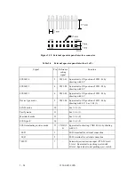
Up to eight SCSI devices can be connected to the SCSI bus. SCSI devices include the host
adapter, the optical disk drive, and other SCSI equipment.
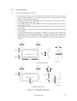
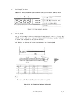
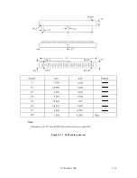
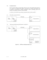
The connector (socket) for the SCSI cable must be an unshielded 50-contact socket with two
rows of 25 contacts on 2.54 mm (0.1 inch) centers. The connector should also be polarized or
keyed to prevent misinsertion. (See Figure 3.17.)
Summary of Contents for MCE3064SS
Page 1: ...C156 E097 01EN MCE3064SS MCF3064SS OPTICAL DISK DRIVES PRODUCT MANUAL ...
Page 3: ...This page is intentionally left blank ...
Page 31: ...This page is intentionally left blank ...
Page 52: ...C156 E097 01EN 2 21 Figure 2 3 Example of alternate processing ...
Page 53: ...This page is intentionally left blank ...
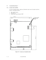
Page 72: ...C156 E097 01EN 3 19 Figure 3 17 SCSI cable connector ...
Page 81: ...This page is intentionally left blank ...
Page 97: ...4 16 C156 E097 01EN Figure 4 5 SCSI connection check 2 ...
Page 99: ...This page is intentionally left blank ...
Page 113: ...This page is intentinally left blank ...
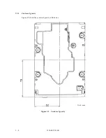
Page 119: ...7 2 C156 E097 01EN Host system A Host system B Figure 7 1 Example of SCSI configuration ...
Page 133: ...7 16 C156 E097 01EN Figure 7 6 ARBITRATION phase ...
Page 135: ...7 18 C156 E097 01EN µ Figure 7 7 SELECTION phase 30 30 30 30 ...
Page 141: ...7 24 C156 E097 01EN Figure 7 10 Transfer in asynchronous mode 18 18 ...
Page 145: ...7 28 C156 E097 01EN Figure 7 11 Transfer in synchronous mode 11 11 11 11 43 18 43 18 ...
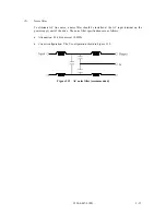
Page 146: ...C156 E097 01EN 7 29 Figure 7 12 Transfer in FAST SCSI mode ...
Page 148: ...C156 E097 01EN 7 31 Figure 7 13 Data transfer rate in asynchronous mode ...
Page 158: ...C156 E097 01EN 7 41 Figure 7 17 RESET condition ...
Page 160: ...C156 E097 01EN 7 43 Figure 7 18 Bus phase sequence 1 of 2 ...
Page 161: ...7 44 C156 E097 01EN Figure 7 18 Bus phase sequence 2 of 2 ...
Page 167: ...This page is intentionally left blank ...
Page 171: ...This page is intentionally left blank ...
Page 181: ......


