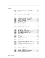
Contents
x C156-E228-02EN
3.1.1 Temperature measurement points........................................................ 3-1
3.1.2 Temperature
requirements................................................................... 3-2
3.1.3 Temperature
rise.................................................................................. 3-3
3.1.4 Air
flow ............................................................................................... 3-4
3.1.5 Air
cleanliness ..................................................................................... 3-4
3.2 Mounting Requirements ........................................................................... 3-4
3.2.1 Outer
dimensions................................................................................. 3-4
3.2.2 Installation
direction.......................................................................... 3-10
3.2.3 Center of gravity................................................................................ 3-11
3.2.4 Precautions on mounting ................................................................... 3-12
3.3 Power Supply Requirements................................................................... 3-14
3.4 Connection Requirement ........................................................................ 3-17
3.4.1 Connectors and terminals .................................................................. 3-17
3.4.2 Cable connection requirements ......................................................... 3-19
3.4.3 External operator panel ..................................................................... 3-20
3.4.4 External operator panel settings (CNH2) .......................................... 3-23
CHAPTER 4
Installation ...............................................................................4-1
4.1 Notes on Drive Handling .......................................................................... 4-1
4.2 Connection Modes .................................................................................... 4-4
4.3 Settings...................................................................................................... 4-5
4.3.1 Setting switches (SW1) ....................................................................... 4-7
4.3.2 Setting of supplying power to SCSI terminating resistor .................. 4-10
4.3.3 SCSI terminating resistor mode......................................................... 4-11
4.4 Mounting................................................................................................. 4-12
4.4.1 Checks before mounting the drive..................................................... 4-12
4.4.2 Mounting
procedure .......................................................................... 4-13
4.5 Cable Connections .................................................................................. 4-13
4.6 Operation Confirmation and Preparation for Use after Installation ....... 4-14
4.6.1 Confirming initial operations ............................................................ 4-14
4.6.2 SCSI connection check...................................................................... 4-15
4.7 Dismounting Drive.................................................................................. 4-17
Summary of Contents for MCM3064SS
Page 1: ...C156 E228 02EN MCM3064SS MCM3130SS MCP3064SS MCP3130SS OPTICAL DISK DRIVES PRODUCT MANUAL ...
Page 4: ...This page is intentionally left blank ...
Page 8: ...This page is intentionally left blank ...
Page 20: ...This page is intentionally left blank ...
Page 30: ...This page is intentionally left blank ...
Page 42: ...Specifications 2 12 C156 E228 02EN Figure 2 3 Example of alternate processing ...
Page 47: ...3 2 Mounting Requirements C156 E228 02EN 3 5 Figure 3 2 Outer dimensions 1 of 2 ...
Page 49: ...3 2 Mounting Requirements C156 E228 02EN 3 7 Figure 3 3 Outer dimensions 1 of 3 ...
Page 51: ...3 2 Mounting Requirements C156 E228 02EN 3 9 Figure 3 3 Outer dimensions 3 of 3 ...
Page 82: ...Installation 4 16 C156 E228 02EN Figure 4 6 SCSI connection check ...
Page 84: ...This page is intentionally left blank ...
Page 98: ...This page is intentionally left blank ...
Page 148: ...SCSI BUS 7 46 C156 E228 02EN Figure 7 21 Bus phase sequence 1 of 2 ...
Page 149: ...7 8 Bus Sequence C156 E228 02EN 7 47 Figure 7 21 Bus phase sequence 2 of 2 ...
Page 158: ...This page is intentionally left blank ...
Page 166: ...This page is intentionally left blank ...
Page 168: ...This page is intentionally left blank ...
Page 169: ......
Page 170: ......


