4.6 Operation Confirmation and Preparation for Use after Installation
C156-E228-02EN 4-15
The BUSY LED is on while the optical disk drive is executing seek,
write, or read operations. The BUSY LED is on momentarily, so it
seems as if it blinked or is off.
The eject motor turns once when the power is turned on so that in
case the spindle motor position deviates due to shocks received by
the drive during transport the position is corrected to allow the
cartridge to be inserted normally. If the cartridge fails to be inserted,
remove the cartridge and turn on the drive power to turn the eject
motor once and reinsert the cartridge.
4.6.2 SCSI connection check
When initial operation checks out normally after the power is turned on, check
whether the drive is correctly connected to the SCSI bus from the host system.
Checking the SCSI connection depends on the host system configuration. This
section describes the general procedure.
(1) Procedure
Figure 4.6 shows the recommended checking procedure.
Note:
Steps a) to c) correspond to a) to c) in Figure 4.6.
a) Issue the TEST UNIT READY command and check that the drive is
connected correctly to the SCSI bus.
b) Use the WRITE BUFFER and READ BUFFER commands to check whether
the SCSI bus operates normally. Use data whose bits change to 0 or 1 at least
once. (Example: A X'00' to X'FF'increment pattern)
c) Check whether the settings are correct. Also, make sure that the controller
and drive operate normally.
Summary of Contents for MCM3064SS
Page 1: ...C156 E228 02EN MCM3064SS MCM3130SS MCP3064SS MCP3130SS OPTICAL DISK DRIVES PRODUCT MANUAL ...
Page 4: ...This page is intentionally left blank ...
Page 8: ...This page is intentionally left blank ...
Page 20: ...This page is intentionally left blank ...
Page 30: ...This page is intentionally left blank ...
Page 42: ...Specifications 2 12 C156 E228 02EN Figure 2 3 Example of alternate processing ...
Page 47: ...3 2 Mounting Requirements C156 E228 02EN 3 5 Figure 3 2 Outer dimensions 1 of 2 ...
Page 49: ...3 2 Mounting Requirements C156 E228 02EN 3 7 Figure 3 3 Outer dimensions 1 of 3 ...
Page 51: ...3 2 Mounting Requirements C156 E228 02EN 3 9 Figure 3 3 Outer dimensions 3 of 3 ...
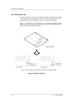
Page 82: ...Installation 4 16 C156 E228 02EN Figure 4 6 SCSI connection check ...
Page 84: ...This page is intentionally left blank ...
Page 98: ...This page is intentionally left blank ...
Page 148: ...SCSI BUS 7 46 C156 E228 02EN Figure 7 21 Bus phase sequence 1 of 2 ...
Page 149: ...7 8 Bus Sequence C156 E228 02EN 7 47 Figure 7 21 Bus phase sequence 2 of 2 ...
Page 158: ...This page is intentionally left blank ...
Page 166: ...This page is intentionally left blank ...
Page 168: ...This page is intentionally left blank ...
Page 169: ......
Page 170: ......


