Interface
5-34
C141-E145-02EN
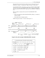
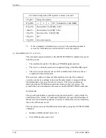
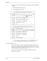
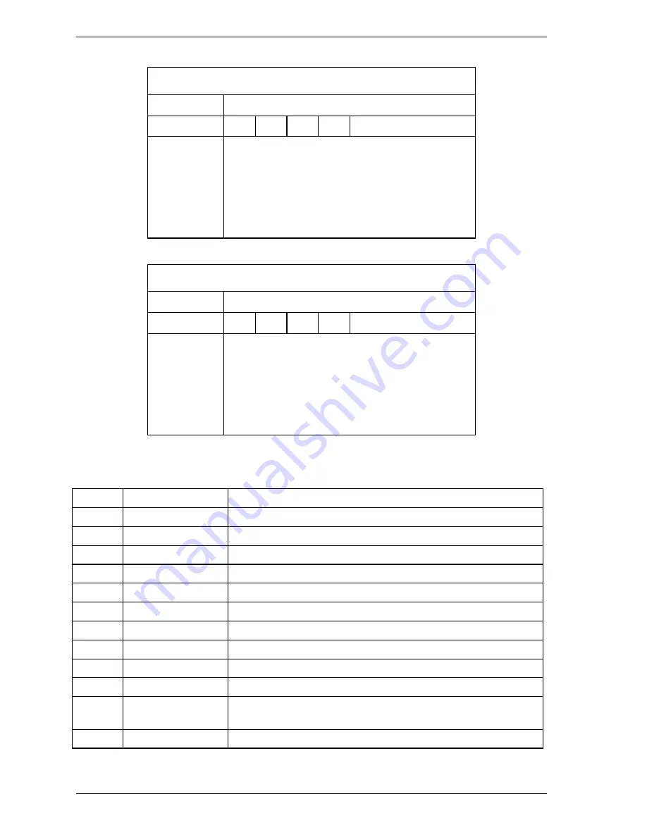
At command issuance (I/O registers setting contents)
1F7
H
(CM)
1
1
1
0
1
1
0
0
1F6
H
(DH)
x
x
x
DV
xx
1F5
H
(CH)
1F4
H
(CL)
1F3
H
(SN)
1F2
H
(SC)
1F1
H
(FR)
xx
xx
xx
xx
xx
At command completion (I/O registers contents to be read)
1F7
H
(ST)
Status information
1F6
H
(DH)
x
x
x
DV
xx
1F5
H
(CH)
1F4
H
(CL)
1F3
H
(SN)
1F2
H
(SC)
1F1
H
(ER)
xx
xx
xx
xx
Error information
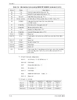
Table 5.4 Information to be read by IDENTIFY DEVICE command (1 of 3)
Word
Value
Description
0
X’045A’
General Configuration *1
1
*2
Number of Logical cylinders *2
2
X’xxxx’
Detailed Configuration *19
3
*2
Number of Logical Heads *2
4-5
X’0000’
Undefined
6
*2
Number of Logical sectors per Logical track *2
7-9
X’0000’
Undefined
10-19
Set by a device
Serial number (ASCII code, 20 characters, right)
20
X’0003’
Undefined
21
X’xxxx’
Buffer Size (1 LSB: 512 Byte)
22
X’0004’
Number of ECC bytes transferred at READ LONG or WRITE
LONG command
23-26
–
Firmware revision (ASCII code, 8 characters, left)
Summary of Contents for MHR2010AT
Page 1: ...C141 E145 02EN MHR2040AT MHR2030AT MHR2020AT MHR2010AT DISK DRIVES PRODUCT MANUAL ...
Page 4: ...This page is intentionally left blank ...
Page 8: ...This page is intentionally left blank ...
Page 10: ...This page is intentionally left blank ...
Page 12: ...This page is intentionally left blank ...
Page 32: ...This page is intentionally left blank ...
Page 38: ...This page is intentionally left blank ...
Page 58: ...Theory of Device Operation 4 6 C141 E145 02EN Figure 4 3 Circuit Configuration ...
Page 188: ...Interface 5 114 C141 E145 02EN g d f f d e Figure 5 7 Normal DMA data transfer ...
Page 240: ...This page is intentionally left blank ...
Page 242: ...This page is intentionally left blank ...
Page 246: ...This page is intentionally left blank ...
Page 248: ...This page is intentionally left blank ...
Page 249: ......
Page 250: ......


