5.3 Host Commands
C141-E145-02EN
5-45
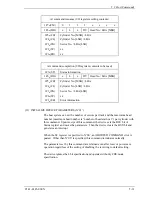
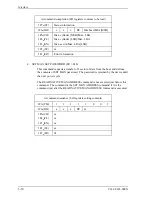
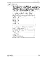
At command issuance (I/O registers setting contents)
1F7
H
(CM)
1
1
1
0
1
1
1
1
1F6
H
(DH)
x
x
x
DV
xx
1F5
H
(CH)
1F4
H
(CL)
1F3
H
(SN)
1F2
H
(SC)
1F1
H
(FR)
xx
xx
xx
xx or *1~3
[See Table 5.5]
At command completion (I/O registers contents to be read)
1F7
H
(ST)
Status information
1F6
H
(DH)
x
x
x
DV
xx
1F5
H
(CH)
1F4
H
(CL)
1F3
H
(SN)
1F2
H
(SC)
1F1
H
(ER)
xx
xx
xx
xx
Error information
*1) Data Transfer Mode
The host sets X’03’ to the Features register. By issuing this command with
setting a value to the Sector Count register, the transfer mode can be selected.
Upper 5 bits of the Sector Count register defines the transfer type and lower 3 bits
specifies the binary mode value.
The IDD supports following values in the Sector Count register value. If other
value than below is specified, an ABORTED COMMAND error is posted.
PIO default transfer mode
00000 000 (X’00’)
PIO flow control transfer mode X
00001 000 (X’08’: Mode 0)
00001 001 (X’09’: Mode 1)
00001 010 (X’0A’: Mode 2)
00001 011 (X’0B’: Mode 3)
00001 100 (X’0C’: Mode 4)
Summary of Contents for MHR2010AT
Page 1: ...C141 E145 02EN MHR2040AT MHR2030AT MHR2020AT MHR2010AT DISK DRIVES PRODUCT MANUAL ...
Page 4: ...This page is intentionally left blank ...
Page 8: ...This page is intentionally left blank ...
Page 10: ...This page is intentionally left blank ...
Page 12: ...This page is intentionally left blank ...
Page 32: ...This page is intentionally left blank ...
Page 38: ...This page is intentionally left blank ...
Page 58: ...Theory of Device Operation 4 6 C141 E145 02EN Figure 4 3 Circuit Configuration ...
Page 188: ...Interface 5 114 C141 E145 02EN g d f f d e Figure 5 7 Normal DMA data transfer ...
Page 240: ...This page is intentionally left blank ...
Page 242: ...This page is intentionally left blank ...
Page 246: ...This page is intentionally left blank ...
Page 248: ...This page is intentionally left blank ...
Page 249: ......
Page 250: ......

