Interface
5-46
C141-E145-02EN
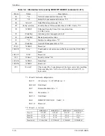
Multiword DMA transfer mode X
00100 000 (X’20’: Mode 0)
00100 001 (X’21’: Mode 1)
00100 010 (X’22’: Mode 2)
Ultra DMA transfer mode X
01000 000 (X’40’: Mode 0)
01000 001 (X’41’: Mode 1)
01000 010 (X’42’: Mode 2)
01000 011 (X’43’: Mode 3)
01000 100 (X’44’: Mode 4)
01000 101 (X’45’: Mode 5)
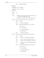
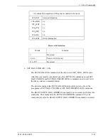
*2) Advanced Power Management (APM)
The host writes the Sector Count register with the desired power management
level and executes this command with the Features register X’05’, and then
Advanced Power Management is enabled.
The drive automatically shifts to power saving mode up to the specified APM
level when the drive does not receive any command for a specific time. The
power management level is shifted from Active Idle, and Low power Idle to
Standby. The Mode-2 takes the maximum shifting time in the APM level. The
APM level setting is preserved by the drive across power on, hardware and
software resets.
APM Level
Sector Count register
Mode-0
Active Idle
Mode-1
Low Power Idle
Mode-2
Standby
Reserved
C0h-FEh
80h-BFh
01h-7Fh
FFh, 00h
Active Idle
: The spindle motor is rotating and heads are loaded on
the medium.
Low Power Idle
: The spindle motor is rotating and heads are unloaded
from the ramp.
Standby
: The spindle motor is not rotating and heads are
unloaded from the ramp.
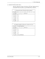
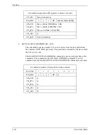
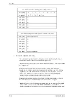
*3) Automatic Acoustic Management (AAM)
The host writes to the Sector Count register with the requested acoustic
management level and executes this command with subcommand code 42h, and
then Automatic Acoustic Management is enabled. The AAM level setting is
preserved by the drive across power on, hardware and software resets.
Summary of Contents for MHR2010AT
Page 1: ...C141 E145 02EN MHR2040AT MHR2030AT MHR2020AT MHR2010AT DISK DRIVES PRODUCT MANUAL ...
Page 4: ...This page is intentionally left blank ...
Page 8: ...This page is intentionally left blank ...
Page 10: ...This page is intentionally left blank ...
Page 12: ...This page is intentionally left blank ...
Page 32: ...This page is intentionally left blank ...
Page 38: ...This page is intentionally left blank ...
Page 58: ...Theory of Device Operation 4 6 C141 E145 02EN Figure 4 3 Circuit Configuration ...
Page 188: ...Interface 5 114 C141 E145 02EN g d f f d e Figure 5 7 Normal DMA data transfer ...
Page 240: ...This page is intentionally left blank ...
Page 242: ...This page is intentionally left blank ...
Page 246: ...This page is intentionally left blank ...
Page 248: ...This page is intentionally left blank ...
Page 249: ......
Page 250: ......


