5.3 Host Commands
C141-E145-02EN
5-69
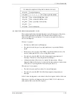
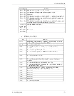
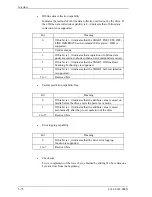
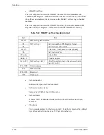
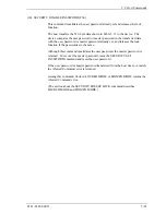
Table 5.7 Features Register values (subcommands) and functions (2 of 3)
Features Resister
Function
X’D5’
SMART Read Log Sector:
A device which receives this sub-command asserts the BSY bit, then reads
the log sector specified in the SN register. Next, it clears the BSY bit and
transmits the log sector to the host computer.
SN:
Log sector
00h:
SMART log directory
01h:
SMART summary error log
02h:
SMART comprehensive error log
06h:
SMART self test log
80h-9Fh: Host vendor log
*
See Table 5.11 concerning the SMART error log data format.
See Table 5.12 concerning the SMART self test log data format.
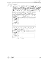
X’D6’
SMART Write Log Sector:
A device which receives this sub-command asserts the BSY bit and when it
has prepared to receive data from the host computer, it sets DRQ and clears
the BSY bit. Next, it receives data from the host computer and writes the
specified log sector in the SN register.
SN:
Log sector
80h-9Fh: Host vendor log
*
The host can write any desired data in the host vendor log.
X’D8’
SMART Enable Operations:
This subcommand enables the failure prediction feature. The setting is
maintained even when the device is turned off and then on.
When the device receives this subcommand, it asserts the BSY bit, enables
the failure prediction feature, then clears the BSY bit.
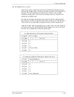
X’D9’
SMART Disable Operations:
This subcommand disables the failure prediction feature. The setting is
maintained even when the device is turned off and then on.
When the device receives this subcommand, it asserts the BSY bit, disables
the failure prediction feature, then clears the BSY bit.
Summary of Contents for MHR2010AT
Page 1: ...C141 E145 02EN MHR2040AT MHR2030AT MHR2020AT MHR2010AT DISK DRIVES PRODUCT MANUAL ...
Page 4: ...This page is intentionally left blank ...
Page 8: ...This page is intentionally left blank ...
Page 10: ...This page is intentionally left blank ...
Page 12: ...This page is intentionally left blank ...
Page 32: ...This page is intentionally left blank ...
Page 38: ...This page is intentionally left blank ...
Page 58: ...Theory of Device Operation 4 6 C141 E145 02EN Figure 4 3 Circuit Configuration ...
Page 188: ...Interface 5 114 C141 E145 02EN g d f f d e Figure 5 7 Normal DMA data transfer ...
Page 240: ...This page is intentionally left blank ...
Page 242: ...This page is intentionally left blank ...
Page 246: ...This page is intentionally left blank ...
Page 248: ...This page is intentionally left blank ...
Page 249: ......
Page 250: ......

