5.3 Host Commands
C141-E145-02EN
5-23
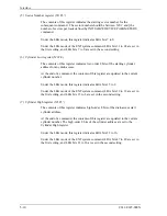
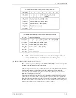
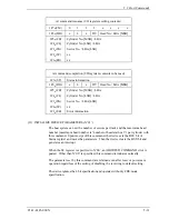
At command issuance (I/O registers setting contents)
1F7
H
(CM)
1
1
0
0
1
0
0
R
1F6
H
(DH)
x
L
x
DV
Start head No. / LBA
[MSB]
1F5
H
(CH)
1F4
H
(CL)
1F3
H
(SN)
1F2
H
(SC)
1F1
H
(FR)
Start cylinder No. [MSB] / LBA
Start cylinder No. [LSB] / LBA
Start sector No. / LBA [LSB]
Transfer sector count
xx
At command completion (I/O registers contents to be read)
1F7
H
(ST)
Status information
1F6
H
(DH)
x
L
x
DV
End head No. / LBA [MSB]
1F5
H
(CH)
1F4
H
(CL)
1F3
H
(SN)
1F2
H
(SC)
1F1
H
(ER)
End cylinder No. [MSB] / LBA
End cylinder No. [LSB] / LBA
End sector No. / LBA [LSB]
00 (*1)
Error information
*1
If the command is terminated due to an error, the remaining number of
sectors of which data was not transferred is set in this register.
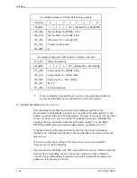
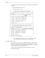
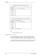
(4) READ VERIFY SECTOR(S) (X’40’ or X’41’)
This command operates similarly to the READ SECTOR(S) command except that
the data is not transferred to the host system.
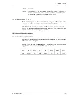
After all requested sectors are verified, the device clears the BSY bit of the Status
register and generates an interrupt. Upon the completion of the command
execution, the command block registers contain the cylinder, head, and sector
number of the last sector verified.
If an unrecoverable error occurs, the verify operation is terminated at the sector
where the error occurred. The command block registers contain the cylinder, the
head, and the sector addresses (in the CHS mode) or the logical block address (in
the LBA mode) of the sector where the error occurred. The Sector Count register
indicates the number of sectors that have not been verified.
Summary of Contents for MHR2010AT
Page 1: ...C141 E145 02EN MHR2040AT MHR2030AT MHR2020AT MHR2010AT DISK DRIVES PRODUCT MANUAL ...
Page 4: ...This page is intentionally left blank ...
Page 8: ...This page is intentionally left blank ...
Page 10: ...This page is intentionally left blank ...
Page 12: ...This page is intentionally left blank ...
Page 32: ...This page is intentionally left blank ...
Page 38: ...This page is intentionally left blank ...
Page 58: ...Theory of Device Operation 4 6 C141 E145 02EN Figure 4 3 Circuit Configuration ...
Page 188: ...Interface 5 114 C141 E145 02EN g d f f d e Figure 5 7 Normal DMA data transfer ...
Page 240: ...This page is intentionally left blank ...
Page 242: ...This page is intentionally left blank ...
Page 246: ...This page is intentionally left blank ...
Page 248: ...This page is intentionally left blank ...
Page 249: ......
Page 250: ......


