C141-E034-02EN
5 - 18
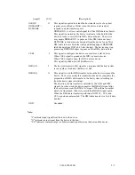
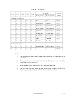
At command completion (I/O registers contents to be read)
1F7
H
(ST)
Status information
1F6
H
(DH)
×
L
×
DV
End head No. /LBA [MSB]
1F5
H
(CH)
1F4
H
(CL)
1F3
H
(SN)
1F2
H
(SC)
1F1
H
(ER)
End cylinder No. [MSB] / LBA
End cylinder No. [LSB]
/ LBA
End sector No.
/ LBA [LSB]
00 (*1)
Error information
*1 If the command is terminated due to an error, the remaining number of
sectors of which data was not transferred is set in this register.
(2)
READ MULTIPLE (X'C4')
This command operates similarly to the READ SECTOR(S) command. The device does not
generate an interrupt (assertion of the INTRQ signal) on each every sector. An interrupt is
generated after the transfer of a block of sectors for which the number is specified by the SET
MULTIPLE MODE command.
The implementation of the READ MULTIPLE command is identical to that of the READ
SECTOR(S) command except that the number of sectors is specified by the SET MULTIPLE
MODE command are transferred without intervening interrupts. In the READ MULTIPLE
command operation, the DRQ bit of the Status register is set only at the start of the data block, and
is not set on each sector.
The number of sectors (block count) to be transferred without interruption is specified by the SET
MULTIPLE MODE command. The SET MULTIPLE MODE command should be executed prior
to the READ MULTIPLE command.
When the READ MULTIPLE command is issued, the Sector Count register contains the number of
sectors requested (not a number of the block count or a number of sectors in a block).
Upon receipt of this command, the device executes this command even if the value of the Sector Count
register is less than the defined block count (the value of the Sector Count should not be 0).
If the number of requested sectors is not divided evenly (having the same number of sectors [block
count]), as many full blocks as possible are transferred, then a final partial block is transferred.
The number of sectors in the partial block to be transferred is n where n = remainder of ("number
of sectors"/"block count").
If the READ MULTIPLE command is issued before the SET MULTIPLE MODE command is
executed or when the READ MULTIPLE command is disabled, the device rejects the READ
MULTIPLE command with an ABORTED COMMAND error.
If an error occurs, reading sector is stopped at the sector where the error occurred. Command
block registers contain the cylinder, the head, the sector addresses (in the CHS mode) or the logical
block address (in the LBA mode) of the sector where the error occurred, and remaining number of
sectors that had not transferred after the sector where the error occurred.
An interrupt is generated when the DRQ bit is set at the beginning of each block or a partial block.
Summary of Contents for MPA3017AT
Page 1: ...C141 E034 02EN MPA3017AT MPA3026AT MPA3035AT MPA3043AT MPA3052AT DISK DRIVES PRODUCT MANUAL ...
Page 29: ...C141 E034 02EN 3 2 Figure 3 1 Dimensions ...
Page 44: ...C141 E034 02EN 4 5 Figure 4 2 MPA30xxAT Block diagram ...
Page 50: ...C141 E034 02EN 4 11 Figure 4 4 Read write circuit block diagram ...
Page 52: ...C141 E034 02EN 4 13 Figure 4 6 PR4 signal transfer ...


