background image

E-22

CONNECTING THE DISPLAY TO EXTERNAL EQUIPMENT (Continued)

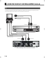
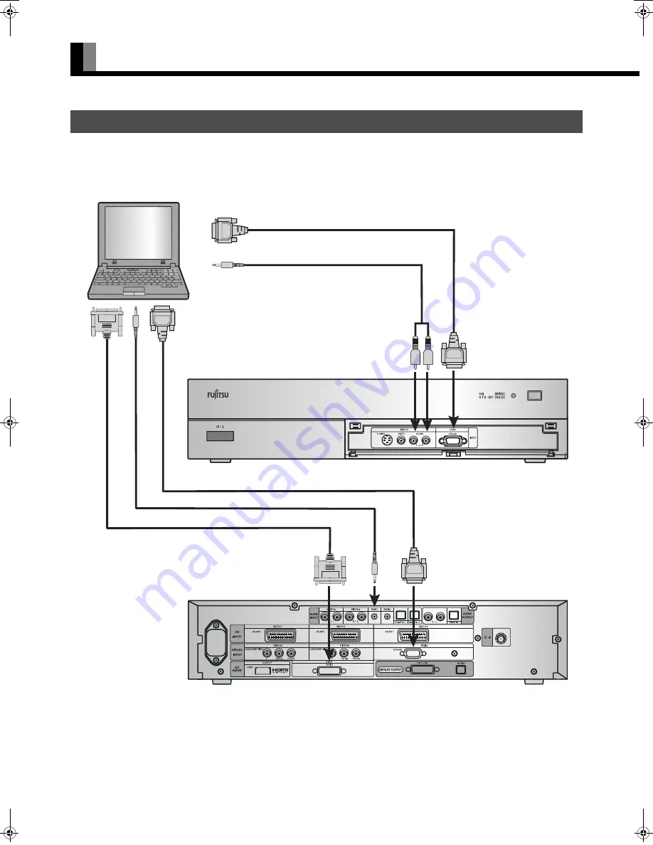
• As the cable for connecting a PC differs with the PC model, please consult your dealer for information on the right cable to purchase. 
• The PC can be connected to either the front side or the rear side, whichever is most convenient.

PC

To audio input

To RGB output (mD-sub)

To RGB output (DVI-D)

To audio output

To mD-sub input

To DVI-D input

When connecting to the front side of the AV Selector

To audio input

To RGB output (mD-sub)

To audio output

To mD-sub input

When connecting to the rear side of the AV Selector

MHD01862_E.book  22 ページ  2005年6月14日 火曜日 午前11時50分

Summary of Contents for Plasmavision P-TU4240G

Page 1: ...47 SPECIFICATION E 48 CLEANING AND MAINTENANCE E 50 Before using the display read this manual carefully so that you know how to use the display correctly Refer to this manual whenever questions or problems about operation arise Be sure to read and observe the safety precautions see the separate Safety Precautions manual Keep this manual where the user can see it easily Installation and removal req...

Page 2: ...as it may be hot Contact your dealer if you find that the display does not seem to function properly when used with other audio visual equipment You may need to move your display if it produces degraded pictures or noise due to electromagnetic radiation or if the infrared remote control does not function properly Pictures may not be displayed properly if you connect a non standard PC to the RGB in...

Page 3: ...Section CHECKING ACCESSORIES One power cable One System cable picture One System cable audio Two small ferrite cores One big ferrite core No SFT 72SN Mfr TKK No ZCAT1518 0730 Mfr TDK Two AA batteries One remote control One power cable Two user s manuals Manual Manual One big ferrite core No SFT 72SN Mfr TKK ...

Page 4: ...Make sure that the display is installed in a location where the temperature can be maintained between 0 C and 40 C Never attempt to tilt the display sideways or backward To prevent the power and other cables from being accidentally pulled make sure that they run along the wall or through corners To prevent accidents and ensure safety in the event of an earthquake secure the display to prevent it f...

Page 5: ...tton MODE Input mode selector button MODE Switches between picture input modes VOL button VOL button Adjusts the audio volume Wide screen selector button WIDE Switches the screen over to a desired wide screen ON OFF button Turns the power ON and OFF standby state Ambient Sensor Detects the brightness of external light Do not obstruct it Warning If the power indicator lamp flashes red or green this...

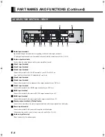
Page 6: ... terminal Connect this terminal to the display output picture terminal on the AV Selector using the special cable provided Display input audio terminal Connect this terminal to the display output audio terminal on the AV Selector using the special cable provided External speaker output terminal EXT SP Connect this terminal to the optionally available speaker When connecting a cable attach a ferrit...

Page 7: ...r is still supplied to parts even if the indicator lamp is off Video3 S video input terminal Connect this terminal to the S video output terminal of your video camera etc Video3 video input terminal Connect this terminal to the video output terminal of your video camera etc Audio input terminals L R These are the audio input terminals for the Video3 and RGB3 terminals Input the audio for the video...

Page 8: ...inal Connect this terminal to the component video output terminal of your DVD etc Video7 input terminal Connect this terminal to the HDMI output terminal of your DVD etc RGB1 input terminal Connect this terminal to the monitor DVI D output terminal of your PC RGB2 input terminal Connect this terminal to the monitor mD sub output terminal of your PC Display output terminals Picture Audio Connect th...

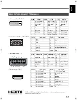
Page 9: ...Input signal 1 Red 9 2 Green 10 Ground 3 Blue 11 4 12 5 Ground 13 Horizontal synchronization 6 Ground 14 Vertical synchronization 7 Ground 15 8 Ground Frame Ground 2 6 10 14 18 3 7 11 15 19 4 8 12 16 20 1 5 9 13 17 21 SCART terminal Video1 2 4 Pin No Input Signal Pin No Input Signal Pin No Input Signal 1 8 15 Red chrominance 2 Right audio 9 Green ground 16 3 10 17 4 Audio ground 11 Green 18 Compos...

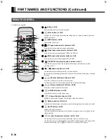
Page 10: ...n the teletext broadcastings input the 3 digits for the required teletext page to change the page Channel Up Down buttons Î E 26 Press these buttons to select the preset programs Use these buttons to scroll through a page in the teletext broadcasting Volume adjustment buttons Î E 25 Press these buttons to adjust the volume AUDIO IN button Î E 29 Press this button to select the audio input Channel ...

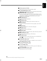
Page 11: ...you are currently watching SIZE button Press this button to change the size of the current watching page INDEX button Press this button to return to the INDEX page MODE button Switches to the LIST mode Press this button once again to return to the current mode STORE button Î E 27 In LIST mode saves the current display to the Favorites page CANCEL button Press this button to watch the terrestrial b...

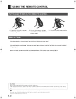
Page 12: ...E CONTROL 1 To remove the cover slide it outwards while pressing it down 2 Place two AA batteries in the remote control Make sure that the batteries are properly oriented 3 Close the cover until it snaps into place PRECAUTIONS CAUTION Be sure to use replacement batteries of the same type as the original ones When disposing of used batteries please comply with governmental regulations or environmen...

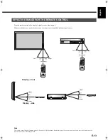
Page 13: ...cles between the remote control and the display s signal receiver EFFECTIVE RANGE FOR THE REMOTE CONTROL Left Display front Display side Upper Lower Right 5 m Front Left Right 5 m Front Upper Lower Note The remote control may not function properly if you use a high frequency fluorescent lamp If you experience problems move the lamp or use the remote control from a different position ...

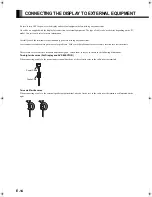
Page 14: ...Loose connectors can result in picture or color problems Make sure that all connectors are securely inserted into their terminals These ferrite cores are used to attenuate undesired signals Attach them correctly as shown in the following illustrations Two big ferrite cores For Display and AV SELECTOR When connecting a cable to the power input terminal attach one of these ferrite cores to the cable...

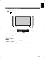
Page 15: ...tion cable For details see page E 16 2 Antenna line See page E 17 for further details 3 Speakers For how to connect speakers see the instructions provided with the speakers 2 Connecting the power cord Connect the power plug of the display and AV Selector power cords to a grounded 3 pin outlet BASIC SYSTEM CONNECTIONS Display Speaker optional To AC outlet AV Selector Antenna commercially available ...

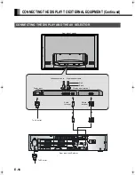
Page 16: ...PMENT Continued CONNECTING THE DISPLAY AND THE AV SELECTOR Rear side of display Left speaker cable Right speaker cable Red Black Power input Display input terminal To AC outlet Audio terminal Picture terminal Rear side of AV Selector To AC outlet ...

Page 17: ... Connects to the antenna input terminal on the AV Selector rear panel Please enquire with your local teletext broadcasting company if you want to receive teletext broadcasts CONNECTING THE ANTENNA Antenna commercially available product To the antenna input AV Selector rear panel ...

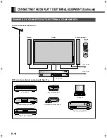
Page 18: ... Speaker Display Speaker optional Remote control VCR Î E 19 DVD recorder player Î E 20 PC Î E 22 VCR or other external components See P Î AV Selector Audio amplifier Î E 23 Video camera Î E 21 Videogame machine Î E 21 Satellite tuner Î E 20 Antenna commercially available product To AC outlet To AC outlet ...

Page 19: ...RT terminal VCR To SCART output To SCART input Rear side of AV selector Note Unplug the power cord from the AC outlet before you connect external components Also refer to the instructions for the component to be connected When inputting audio connect to the terminals corresponding to the used video input or RGB input ...

Page 20: ...put terminal the HDMI input terminal or the SCART terminal If the component to be connected is equipped with HDMI output terminal or the component video output terminal connection to either of these terminals is recommended DVD RECORDER PLAYER SATELLITE TUNER To audio outputs To component video output To SCART output To audio inputs To SCART input To component video input Rear side of AV Selector ...

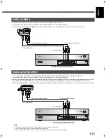
Page 21: ...e screen for an extended period If the same image is displayed on the screen for an extended period the brightness of that part of the screen may change and image burn in may leave an after image on the screen If the videogame machine to be connected is equipped with S video output terminal it is recommended to connect to the S video terminal VIDEO CAMERA VIDEOGAME MACHINE To video and audio outpu...

Page 22: ...o purchase The PC can be connected to either the front side or the rear side whichever is most convenient PC To audio input To RGB output mD sub To RGB output DVI D To audio output To mD sub input To DVI D input When connecting to the front side of the AV Selector To audio input To RGB output mD sub To audio output To mD sub input When connecting to the rear side of the AV Selector ...

Page 23: ...uency of 48 kHz In the case of outputs with another frequency connect to an audio system amplifier WHEN OUTPUTTING AUDIO SIGNALS TO AN AUDIO AMPLIFIER Rear side of AV Selector To digital audio input To analog audio input To digital audio output To analog audio output Note Unplug the power cord from the AC outlet before you connect external components Also refer to the instructions for the componen...

Page 24: ...hts up 2 Press on the remote control The color of the power lamp changes from Red to Green 3 Press the button of the channel you want to watch and then press or Select TV or the picture mode to input 4 Press when the power is ON The color of the power lamp changes from Green to Red and the display goes into standby state You can also use the buttons on the display s control panel to perform these ...

Page 25: ...s stored even when you turn OFF the power Muting the audio Press The audio is removed Press again to restore the audio to the original level The mute mode can also be released by pressing the volume buttons You can also use the buttons on the display s control panel to perform these steps When the volume adjustment button is pressed Note Functions may not be available with some models and some dev...

Page 26: ...is received 3 Select the Program No Press The program changes to the selected Program No Select your desired Program No 0 to 99 Even if you press the Program No can be changed as shown below Available in TV mode The program numbers set to skip over are not shown on the display See page E 40 for details CH Return Press The program returns to the previous program or Video mode or RGB mode that you w...

Page 27: ...digit number by and is pressed Storing and displaying favorite teletext programs 1 Press to select the LIST mode 2 Press or to select the color button for storing the teletext page program 3 Press for three seconds at least to store the displaying teletext program to the color button During the storing operation the color button momentarily turns white 4 In the LIST mode press or to display the st...

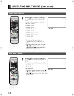
Page 28: ...e VIDEO mode by pressing during Video indication on the screen by pressing when selected On in ON SCREEN MENU P E 39 RGB INPUT MODE 1 Press to select the input mode You can select between the modes from RGB1 to RGB3 The input terminal of each RGB mode is as follows RGB1 DVI D RGB2 mD sub RGB3 mD sub You can also change RGB mode by pressing during RGB indication on the screen by pressing when selec...

Page 29: ...8 Each time this button is pressed the setting changes as follows For the picture memory settings see Setting Picture Memory P E 35 Audio In Press Switches the input audio Each time this button is pressed the input changes as follows The digital audio input terminal on the display complies with a sampling frequency of 48 kHz In the case of outputs with another frequency connect to an audio system ...

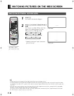
Page 30: ...me may cause phosphor burn in A variety of Screen Sizes are available with this display Remember that if you select a mode with an aspect ratio ratio of frame width to frame height different from that of the TV program or video media the pictures will appear differently than if you had selected a mode having the same aspect ratio Showing a movie or similar premium event at a different aspect ratio...

Page 31: ... reduced not the height of the caption Captions may not be easy to read however depending on the picture The following aspect ratios are available 4 3 aspect ratio 16 9 aspect ratio VHF UHF broadcasting BS broadcasting HDTV broadcasting 1 85 1 aspect ratio 2 35 1 aspect ratio Vista Vision size Cinema Vision size SCREEN SIZE ASPECT RATIO Picture of standard size Wide1 Vertically extended picture Wi...

Page 32: ...efault Treble E 37 Bass E 37 Balance E 37 Loudness E 37 Adjustment E 38 Dot Clock E 38 On Screen Menu E 39 Clock Phase E 38 Input Terminal E 40 Clamp Position E 38 Channel Setting E 40 Auto Calibration E 38 Others E 41 OSD E 39 Language E 39 Name Select E 39 Video1 E 40 Video2 E 40 Video3 E 40 Video4 E 40 Auto Store E 40 Manual Store E 40 Setting E 40 Sort E 41 Name E 41 Auto Off NO SIG E 41 Scree...

Page 33: ...ar 5 Press or to change tint values More greenish colors More purplish colors 6 Press to store 7 Press when you finish Repeat steps 3 4 5 and 6 when you wish to make changes to other options When is pressed after you have selected Default the settings are returned to those that were valid when you purchased the set Press to halt the operation in progress PICTURE selected in the main menu screen Ti...

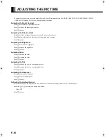
Page 34: ...level and reduce the contrast Press to store Adjusting the Brightness Press to increase the brightness Press to reduce the brightness Press to store Adjusting Color Press to darken the color Press to lighten the color Press to store Adjusting the Tint Press to change the tint to a more greenish color Press to change the tint to a more purplish color Press to store Adjusting the Sharpness Press to ...

Page 35: ...gs can be stored enabling you to quickly switch to your desired group of settings for the picture you are planning to watch Save Use or to select Memory 1 8 If is pressed the current picture adjustment values are stored to the selected Memory Load Use or to select Memory 1 8 When is pressed the values becomes the picture adjustment values stored in the selected Memory Picture Memory Selection Scre...

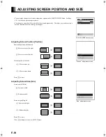
Page 36: ... before making any changes Adjusting Screen Position Position Horizontal position Horizontal Moves screen to the right Moves screen to the left Vertical position Vertical Moves screen up Moves screen down Press to store Adjusting Screen Size Size Screen width Width Increases width Reduces width Screen height Height Increases height Reduces height Press to store You cannot adjust screen size in DVI...

Page 37: ...ress to make adjustments Shifts the volume balance towards the right Shifts the volume balance towards the left Press to store Setting Loudness Loudness Corrects the balance between bass and treble for easy listening even with weak volume Each time you press or one of the available choices appears in the following sequence Press to store AUDIO Menu screen Note The screen display disappears if ther...

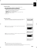
Page 38: ...ion Dot Clock mD sub You may find the vertically striped pattern in pictures depending on the clock frequency of your PC s processor If you experience blurring you can obtain a clearer picture by adjusting the Dot Clock Use to adjust to minimize vertically striped pattern in pictures Clock Phase mD sub Pictures and the outline of letters may blur or flicker as the clock phase of your PC may be dif...

Page 39: ...ortuguês Portuguese Ελλάδα Greek 3 Press The menu is displayed in the selected language Selection of indications Name Select You can change the settings for indications for video inputs and RGB inputs Video input You can change the settings for indications for the VIDEO inputs Select the desired indication in accordance with the connected equipment Each time is pressed the setting is switched In t...

Page 40: ...ems for setting It is switched as shown as below Press to proceed to the next step Auto Store Press or to select the country or region and then press All the channels are scanned and only the channels that can be received are assigned to the Program Nos Several minutes are required to scan all the channels To cancel the operation in progress press See page E 47 for the selectable TV frequencies Ma...

Page 41: ...estination From edit source and or to switch the Program No Press to store Auto Off NO SIG You can make to the standby state automatically when the no signal state continued during set up time Press to select the Time Press to select the amount of time before the standby state starts Press to store The numerical value is the approximate amount of time before the standby state starts You can assign...

Page 42: ...hen the Screen Orbiter function is operated some letters at the top bottom right or left of the screen may be missed Setting RGB Input Signal Compulsorily Direct Setting for RGB You can use this option to switch the setting for RGB input signal Each time you press or one of the available choices appears in the following sequence Auto The optimum display is obtained automatically for input signals ...

Page 43: ...ation status Select Information and press The Information screen will appear Mode Input mode appears at the upper right corner of the screen Freq Scan Mode Frequency scanning Input Signal Video mode Input Sync Signal type Freq Synchronized signal frequency polarity Preset No RGB code number Information screen Video Mode Information screen RGB Mode Status Display Screen TV Mode Note The screen disp...

Page 44: ...nce PICTURE POSITION SIZE AUDIO FEATURES FACTORY DEFAULT The FACTORY DEFAULT Menu screen will appear 3 Press Displays the message of whether to proceed with the initialization 4 Press or to select the Yes 5 Press The message of having completed the initialization will be displayed after initializing 6 Press when you finish FACTORY DEFAULT selected in the main menu screen Displays the message of wh...

Page 45: ...5 mounting angle P CT4200 for 42 model 50 model Desktop Stand unit P TT4202 for 42 model 50 model Speaker 1 set of 2 speakers P SP1000 for attaching to the 42 model 50 model P SP4200 for mounting on the speaker stands for 42 model P SP5010 for mounting on the speaker stands for 50 model Desktop Speaker Stand 1 set of 2 speaker stands P ST4200 for P SP4200 P ST5000 for P SP5010 Warning To prevent i...

Page 46: ... 480 31 47 59 94 VGA 640 x 480 37 50 75 00 VGA 75 Hz 640 x 480 43 27 85 01 VGA 85 Hz 720 x 400 31 47 70 09 400 lines 800 x 600 37 88 60 32 SVGA 60 Hz 800 x 600 46 88 75 00 SVGA 75 Hz 800 x 600 53 67 85 06 SVGA 85 Hz 1024 x 768 48 36 60 00 XGA 60 Hz 1024 x 768 60 02 75 03 XGA 75 Hz 1024 x 768 68 68 84 99 XGA 85 Hz 1280 x 1024 63 98 60 02 SXGA 60 Hz 1280 x 1024 79 98 75 03 SXGA 75 Hz 848 x 480 31 02...

Page 47: ...203 25 671 25 231 25 703 25 245 25 719 25 260 75 751 25 252 25 727 25 210 25 679 25 238 25 711 25 252 25 727 25 272 75 759 25 259 25 735 25 217 25 687 25 245 25 719 25 259 25 735 25 284 75 767 25 266 25 743 25 224 25 695 25 252 25 727 25 266 25 743 25 296 75 775 25 273 25 751 25 231 25 703 25 259 25 735 25 273 25 751 25 303 25 783 25 280 25 759 25 238 25 711 25 266 25 743 25 280 25 759 25 311 25 7...

Page 48: ... diagonal Aspect ratio 16 9 wide Number of pixels 1024 H x 1024 V 1366 H x 768 V Weight 31 5 kg 69 lbs 45 kg 99 lbs Outer dimensions 103 9 W x 64 0 H x 8 7 D cm 40 9 W x 25 2 H x 3 4 D inch does not include outer projections 121 6 W x 72 6 H x 10 0 D cm 47 9 W x 28 6 H x 3 9 D inch does not include outer projections Power supply 110 240 VAC 50 60 Hz Current rating 4 2 1 8 A 4 4 1 9 A External equi...

Page 49: ... terminal Video DVI D terminal EIA CEA 861B Compliant Audio Mini pin jack 0 5 Vrms Left Right RGB 2 input terminal Video mD sub 3 parallel 15 pin 0 7 Vp p 75 Ω Audio Mini pin jack 0 5 Vrms Left Right RGB 3 input terminal Video mD sub 3 parallel 15 pin 0 7 Vp p 75 Ω Audio Same as video 3 input Pin jack 0 5 Vrms Left Right Digital 1 2 audio input terminal Optical input Amplifier output terminal Anal...

Page 50: ...ed when the cabinet expands or contracts due to variations in temper ature This sound does not indicate that the display has a problem The display makes a buzzing sound The display has fans to maintain the temperature of internal components at a constant level This sound is produced by the fan as it rotates Applies to models equipped with a fan There are spots on the screen Check whether your AV e...

Reviews: