background image

Before using the display, read this manual carefully so that you know how to use the display correctly.

Refer to this manual whenever questions or problems about operation arise.  Be sure to read and observe the

safety precautions.

Keep this manual where the user can see it easily.

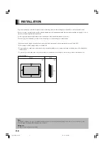
* Installation and removal require special expertise.  Consult your product dealer for details.

Contents

USER’S MANUAL

42”/50” WIDE PLASMA DISPLAY

P42VCA10/P42HCA10/P50XCA10/P42VCA20/
P42VCA11/P42HCA11/P50XCA11/P42VCA21/
P42VCA12/P42HCA12/P50XCA12/P42VCA22

Before Use

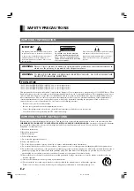
• Safety Precautions ··································· E-2–E-3
• Features ····························································E-4
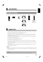
• Accessories ······················································ E-5
• Handy Tips ······················································· E-5
• Installation ······················································· E-6

Usage

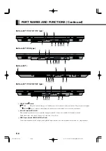
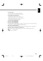
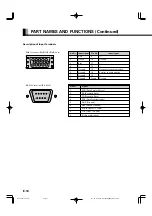
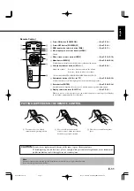
• Part Names and Functions ····················· E-7–E-11
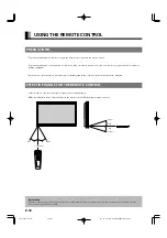
• Using the Remote Control ····························· E-12
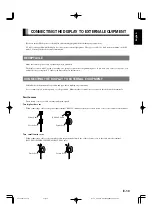
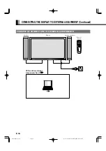
• Connecting the Display to External

Equipment ············································ E-13–E-15

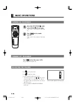
• Basic Operations ············································ E-16
• Selecting Input Mode ····································· E-17
• Watching Pictures on the Wide Screen ··· E-18–E-19

Adjustments

• Adjusting Pictures (PICTURE Menu) ··· E-20–E-21
• Adjusting Screen Position and Size

(POSITION/SIZE Menu) ························ E-22–E-23

• Adjusting Audio (AUDIO Menu) ········· E-24–E-25
• Other Adjustments (FEATURES Menu) ··· E-26–E-33
• Initialization of User Adjustment Value

(FACTORY DEFAULT) ····································· E-34

Others

• Options ···························································· E-35
• Factory Settings ············································ E-36
• Specification ········································· E-37–E-40
• Cleaning and Maintenance ···························· E-41

Page

Page

English

 E-P42VCA10(hyo1)

03.1.14, 10:25 AM

Page 2

Adobe PageMaker 6.5J/PPC

Summary of Contents for Plasmavision P42HCA10

Page 1: ...ety Precautions E 2 E 3 Features E 4 Accessories E 5 Handy Tips E 5 Installation E 6 Usage Part Names and Functions E 7 E 11 Using the Remote Control E 12 Connecting the Display to External Equipment E 13 E 15 Basic Operations E 16 Selecting Input Mode E 17 Watching Pictures on the Wide Screen E 18 E 19 Adjustments Adjusting Pictures PICTURE Menu E 20 E 21 Adjusting Screen Position and Size POSITI...

Page 2: ...into this product observe the following basic rules for its installation use and service Please read these Important Safeguards carefully before use 1 Read these instructions 2 Keep these instructions 3 Heed all warnings 4 Follow all instructions 5 Do not use this apparatus near water 6 Clean only with dry cloth 7 Do not block any ventilation openings Install in accordance with the manufacturer s ...

Page 3: ...int where they exit from the product For added protection for this product during a lightning storm or when it is left unattended and unused for long periods of time unplug it from the wall outlet and disconnect the cable system This will prevent damage to the product due to lightning and power line surges Do not overload wall outlets extension cords or convenience receptacles on other equipment a...

Page 4: ...ed In this case you can set up the display so that on screen information such as input modes and menus is displayed properly Power management function The display features a DPMS Display Power Management Signaling function that ensures automatic power saving capability Flexible as part of a system You can operate the display by remote control using the RS 232C interface If you have two or more dis...

Page 5: ...l equipment You may need to move your display if it produces degraded pictures or noise due to electromagnetic radiation or if the infrared remote control does not function properly Pictures may not be displayed properly if you connect a non standard PC to the RGB input terminal In this case contact your dealer for more information The protective circuit built into the display automatically turns ...

Page 6: ...cation where the temperature can be maintained between 0 C and 40 C Never attempt to tilt the display sideways or backward To prevent the power and other cables from being accidentally pulled be sure to make the wiring work along the wall or through the corners of floor To prevent an accident and ensure safety in the event of an earthquake fix the display securely into position as described below ...

Page 7: ...ding on the type of malfunction See P E 41 for more information 2 Remote control signal receiver Receives signals from the remote control Warning If the power indicator lamp flashes red this signifies that the display has developed a problem When this happens be sure to remove the power plug from the receptacle and contact your dealer Leaving the display power ON can result in fire or electric sho...

Page 8: ...you to control the display from the PC Connect it to the RS 232C terminal on the PC When connecting a cable attach a ferrite core to the cable See P E 13 3 RGB1 input terminal RGB1 INPUT mD sub Connect this terminal to the PC s display analog RGB output terminal or decoder digital broadcast tuner etc output terminal PART NAMES AND FUNCTIONS Continued Bottom 42 VCA 10 11 12 type Bottom 42 HCA type ...

Page 9: ...UT 7 Sound 2 input terminal AUDIO2 INPUT 8 Sound 3 input terminal AUDIO3 INPUT Connect this terminal to the sound output terminal of your computer etc See P E 30 for the selection of audio input for video input This terminal is not available for P42VCA10 P42HCA10 P50XCA10 P42VCA20 9 RGB2 input terminal RGB2 INPUT BNC Connect this terminal to the PC s display analog RGB output terminal or decoder d...

Page 10: ... 7 Ground 15 8 Ground Frame Ground RGB1 terminal RGB1 INPUT mD sub Pin No Signal 1 DCD Data Carrier Detect 2 RD Received Data 3 TD Transmit Data 4 DTR Data Terminal ready 5 GND Ground 6 DSR Data Set Ready 7 RTS Request To send 8 CTS Clear To Send 9 RI Ring Indication RS 232C terminal RS 232C PART NAMES AND FUNCTIONS Continued E P42VCA10 07 15 03 1 14 10 29 AM Page 10 Adobe PageMaker 6 5J PPC ...

Page 11: ...n within a menu 0 Display selector buttons SHIFT 1 4 See P E 32 When you use two or more displays you can use these buttons to control up to four displays by assigning a unique number to each display PUTTING BATTERIES IN THE REMOTE CONTROL Remote Control 1 To remove the cover slide it outwards while pressing it down 2 Place two AA batteries in the remote control Make sure that the batteries are pr...

Page 12: ...zene or thinner EFFECTIVE RANGE FOR THE REMOTE CONTROL Point the remote control at the display s signal receiver when using it Make sure that there are no obstacles between the remote control and the display s signal receiver USING THE REMOTE CONTROL Information The remote control may not function properly if you use a high frequency fluorescent lamp If you experience problems move the lamp or use...

Page 13: ...y check the terminals for position and type before making any connections Loose connectors can result in picture or color problems Make sure that all connectors are securely inserted into their terminals Ferrite cores These ferrite cores are used to attenuate undesired signals Two big ferrite cores When connecting a cable to the power input terminal RS 232C terminal attach one of these ferrite cor...

Page 14: ... EXTERNAL EQUIPMENT Continued EXAMPLE OF CONNECTION TO EXTERNAL COMPONENTS Remote control Display Speaker optional Speaker VCR or other external components See P PC E P42VCA10 07 15 03 1 14 10 29 AM Page 14 Adobe PageMaker 6 5J PPC ...

Page 15: ...GB1 input mD sub Note Unplug the power cord from the AC outlet before you connect external components Also refer to the instructions for the component to be connected When inputting voice see Selecting input terminals page E 30 The sound terminal is not available for P42VCA10 P42HCA10 P50XCA10 P42VCA20 Bottom of Display Ex P42VCA11 series E P42VCA10 07 15 03 1 14 10 29 AM Page 15 Adobe PageMaker 6...

Page 16: ...turns red TURNING OFF THE POWER 1 2 Press to increase the volume Press to reduce the volume Any value between 0 and 40 can be selected No Audio appears if you press or after you have selected No Audio for Audio Input See P E 30 Note that the volume level remains stored even when you turn OFF the power Not used with P42VCA10 P42HCA10 P50XCA10 P42VCA20 ADJUSTING THE VOLUME When the volume adjustment...

Page 17: ...fferent input mode appears The sequence is as follows RGB1 Displays pictures from equipment connected to the RGB1 mD sub terminal RGB2 Displays pictures from equipment connected to the RGB2 BNC x 5 terminal 1 RGB2 mode RGB1 mode English E P42VCA10 16 19 03 1 14 10 30 AM Page 17 Adobe PageMaker 6 5J PPC ...

Page 18: ...ny event site restaurant or bar for profit making purposes or for a public audience may constitute a copyright infringement For films try to select a mode having the same aspect ratio as the original picture this enables the director s original intentions to be preserved Reference See P E 22 E 23 for how to adjust the picture size and position Press The currently selected mode will appear Press to...

Page 19: ...ing BS broadcasting 1 85 1 aspect ratio Vista Vision size 2 35 1 aspect ratio Cinema Vision size 4 3 16 9 1 85 1 2 35 1 English Normal Displays pictures of normal size i e a 4 3 aspect ratio SCREEN SIZE Wide Ideal for displaying vertically extended pictures such as squeezed pictures and recorded HDTV programs Zoom Enlarges horizontally extended pictures equally in all directions to maintain the as...

Page 20: ...ress when you finish Repeat steps 3 4 5 and 6 when you wish to make changes to other options 1 2 BASIC OPERATIONS EX ADJUSTING TINT Tint PICTURE selected in the main menu screen Tint selected in the PICTURE Menu screen You can make changes to all picture adjustment options in the PICTURE Menu The changes you make will be stored for a selected input mode Therefore you need to select a desired input...

Page 21: ...p Press to store Setting User Color Temp User Color Temp Can set up when User is selected in Color Temp Press or to select Red Green or Blue and press or to make adjustment in the range of 0 to 255 Press to store Color Temp setup is switched to User The initial value of User Color Temp is adjusted individually at the factory On screen information disappears if you do not take any action for about ...

Page 22: ... to the right Moves screen to the left Press to store Press when you finish Repeat steps 3 to 7 when you wish to make changes to other options BASIC OPERATION EX ADJUSTING HORIZONTAL DIRECTION OF SCREEN POSITION POSITION SIZE selected from the main menu screen You can make changes to all screen adjustment options in the POSITION SIZE Menu The changes you make will be stored for the selected input ...

Page 23: ... the right Moves screen to the left Vertical position Vertical Moves screen up Moves screen down Press to store Adjusting Screen Size Size Screen width Width Increases width Reduces width Screen height Height Increases height Reduces height Press to store Setting Range Position adjustment screen Size adjustment screen Position Size English Depending on the input signal the adjustment range may dif...

Page 24: ...teps 3 to 6 when you wish to make changes to other options Audio Input menu will not be displayed when No Audio is selected See P E 30 BASIC OPERATION EX ADJUSTING VOLUME BALANCE Balance AUDIO selected in the main menu screen Balance selected in the AUDIO Menu screen You can make changes to all sound adjustment options in the AUDIO Menu The changes you make will be stored for the selected input mo...

Page 25: ...ting Loudness Loudness Corrects the balance between bass and treble for easy listening even with weak volume Each time you press or one of the available choices appears in the following sequence On Off On Corrects bass and treble Off Loudness dose not function adjust AUDIO Treble Bass Balance 0 0 0 On screen information disappears if you do not take any action for about 60 seconds Cannot be set wi...

Page 26: ...nu appears Press or to select Language Press The Language selection screen will appear Press or to select the language Press The menu is displayed in the selected language Press when you finish Repeat steps 3 to 8 when you wish to make changes to other options 1 2 BASIC OPERATION EX SELECTING LANGUAGE Language FEATURES selected in the main menu screen On Screen Menu screen 3 4 5 6 7 Language selec...

Page 27: ...he Clock Phase Use or to select Auto or Manual Auto Makes automatic adjustment Manual Makes manual adjustment Use or to specify a value between 1 and 32 Press to store Adjusting Clamp Position Clamp Position Adjusts clamp pulse in accordance with the input signal received from connected equipment Use or to specify a value between 8 and 8 Press to store Selecting the Optimum Dynamic Range of Images...

Page 28: ...ore Selecting Language Language You can use this option to select the language displayed on the screen 1 Select Language and press The Language selection screen will appear 2 Press or to select your desired language English Deutsch German Español Spanish Français French Italiano Italian Português Portuguese Pycc к и й Russian 3 Press The menu is displayed in the selected language Russian can only ...

Page 29: ...s not mask Number Masks the fringe top bottom right and left of the screen by the number of pixels specified 5 Press to store Selecting D SUB Input D SUB Input You can use this option to select the signal system it will receive to D SUB Input terminal 1 Select D SUB Input and press D SUB Input screen appears 2 Select the signal system to receive Each time you press or one of the available choices ...

Page 30: ...ckground color Press or to select background color Each time you press or one of the available choices appears in the following sequence Black White Black Mutes images in Black background White Mutes images in White background Switches approx 20 seconds after the display stops receiving signals 5 Press to store DPMS selection screen Audio Input selection screen Selecting input terminals Audio Inpu...

Page 31: ...ut mode Each time you press or one of the available choices appears in the following sequence Off Switches between modes normally RGB1 RGB2 Displays pictures when a signal is received through the selected input mode terminal Press to store When using the display occasionally Select a desired amount of time for DPMS Thus when the display does not receive a signal it will automatically display white...

Page 32: ...or each signal Press to store In Auto mode the resolution of VGA WVGA 480P XGA WXGA SXGA and SXGA may not be automatically distinguished Switch to the fixed display when the image is not displayed properly Specifying RGB Input Signal Code Setting You can use this option to specify and display the type of RGB input signal by code number Each time you press or one of the available choices appears in...

Page 33: ...stallation Each time you press or one of the available choices appears in the following sequence 90 Deg Displays text from left to right when the display is installed with the power indicator lamp at the top Normal Displays text normally 90 Deg Displays text from left to right when the display is installed with the power indicator lamp at the bottom Press to store Be sure to make this setup when c...

Page 34: ...age of having completed the initialization will be displayed after initializing Press when you finish 1 2 You can also use the switches on the display s control panel to accomplish these steps FACTORY DEFAULT selected in the main menu screen Displays the message of whether to proceed the initialization 3 4 5 Displays the message of having completed the initialization You can restore the values of ...

Page 35: ...manual are met The colors of options do not match the display colors perfectly Warning To prevent injury fire and electric shock arrange for options to be initially installed or installed at a different location by your dealer CAUTION This display P42VCA10 P42VCA11 P42VCA12 P42HCA10 P42HCA11 P42HCA12 P50XCA10 P50XCA11 P50XCA12 P42VCA20 P42VCA21 P42VCA22 is for use only with Fujitsu General Limited...

Page 36: ...e display receives a signal whose characteristic does not fall within the display s permissible range You can check input signals through Information on the FEATURES Menu screen See P E 33 In order to facilitate the explanations pictures and diagrams in this manual may differ slightly from the actual items All terms i e company and product names used in this document are trademarks or registered t...

Page 37: ...0 7 Vp p 75 Ω B 0 7 Vp p 75 Ω H TTL Level or ANALOG 75 Ω V TTL Level or ANALOG 75 Ω Sound terminals 2 sound input pin jacks L R 3 lines 500 mVrms at least 22 kΩ Control terminal 1 RS 232C connector D sub 9 pin External speaker output terminal Effective max output 10 W 10 W EIAJ 8 Ω Operating conditions Temperature 0 to 40 C 32 to 104 F Humidity 20 to 80 Accessories 1 remote control 2AA batteries 1...

Page 38: ...G 0 7 Vp p 75 Ω B 0 7 Vp p 75 Ω H TTL Level or ANALOG 75 Ω V TTL Level or ANALOG 75 Ω Sound terminals 2 sound input pin jacks L R 3 lines 500 mVrms at least 22 kΩ Control terminal 1 RS 232C connector D sub 9 pin External speaker output terminal Effective max output 10 W 10 W EIAJ 8 Ω Operating conditions Temperature 0 to 40 C 32 to 104 F Humidity 20 to 80 Accessories 1 remote control 2AA batteries...

Page 39: ...inal x 5 R 0 7 Vp p 75 Ω G 0 7 Vp p 75 Ω B 0 7 Vp p 75 Ω H TTL Level or ANALOG 75 Ω V TTL Level or ANALOG 75 Ω Sound terminals 2 sound input pin jacks L R 3 lines 500 mVrms at least 22 kΩ Control terminal 1 RS 232C connector D sub 9 pin External speaker output terminal Effective max output 10 W 10 W EIAJ 8 Ω Operating conditions Temperature 0 to 40 C 32 to 104 F Humidity 20 to 80 Accessories 1 rem...

Page 40: ...RGB1 input mD sub 3 rows 15 pin Picture signal 0 7 Vp p 75 Ω Synchronization signal TTL level RGB2 input BNC terminal x 5 R 0 7 Vp p 75 Ω G 0 7 Vp p 75 Ω B 0 7 Vp p 75 Ω H TTL Level or ANALOG 75 Ω V TTL Level or ANALOG 75 Ω Sound terminals 2 sound input pin jacks L R 3 lines 500 mVrms at least 22 kΩ Control terminal 1 RS 232C connector D sub 9 pin External speaker output terminal Effective max out...

Page 41: ...the receptacle and inform your dealer about how the lamp flashed As explained below the power indicator lamp flashes differently depending on the type of problem Flashes repeatedly Improper supply voltage level Flashes once Malfunction by the fan Flashes twice Excessive temperature Flashes three times or more Other problems CLEANING AND MAINTENANCE Problem Power does not turn ON No pictures are di...

Reviews: