BX900 S1
Service Supplement
39
Replacement routines
Replacing the front docking board
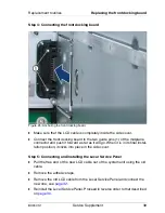
Step 4: Connecting the front docking board
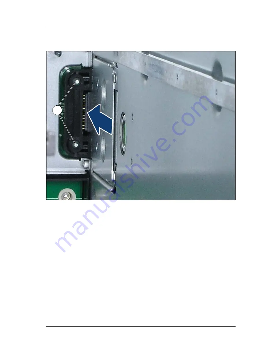
Figure 25: Anchoring the front docking board
Ê
Make sure that the LCD cable is completely inside the side cover.
Ê
Connect the front docking board to the two guide pins (1) of the midplane
connector and push it forward as far as it will go. When it is in its final instal-
lation position, it clicks into place in the side cover.
Step 5: Connecting and installing the Local Service Panel
Ê
Pull the free end of the new LCD cable out of the system unit using the old
cable.
Ê
Remove the adhesive tape.
Ê
Remove the old LCD cable from the Local Service Panel and connect the
new one, see
page 32
.
Ê
Reinstall the Local Service Panel. Proceed in reverse order to that described
on
page 30
.
햲


