40
Operating Manual
CX122
S1
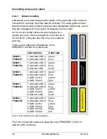
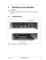
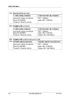
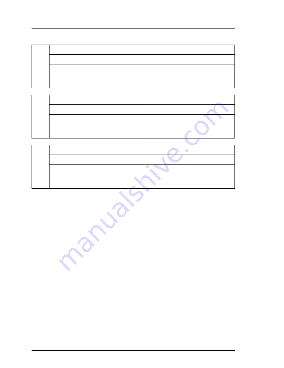
LAN indicators
1/2
Service LAN (onboard)
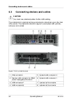
1 LAN activity indicator
2 LAN transfer rate indicator
green ON: Active connection
green FLASHING:
Transmit / Receive activity
OFF: 10 Mbit/s
green ON: 100 Mbit/s
3/4
Gigabit LAN (onboard)
3 LAN activity indicator
4 LAN transfer rate indicator
green ON: Active connection
green FLASHING:
Transmit / Receive activity
OFF: 10 Mbit/s
green ON: 100 Mbit/s
orange ON: 1000 Mbit/s
5/6
7/8
Gigabit LAN (optional expansion card)
5/6 LAN activity indicator
7/8 LAN transfer rate indicator
green ON: Active connection
green FLASHING:
Transmit / Receive activity
OFF: 10 Mbit/s
green ON: 100 Mbit/s
orange ON: 1000 Mbit/s
Summary of Contents for PRIMERGY CX122 S1
Page 1: ...Operating Manual English PRIMERGY CX122 S1 Server Operating Manual Edition November 2010 ...
Page 14: ...14 Operating Manual CX122 S1 Technical data ...
Page 16: ...16 Operating Manual CX122 S1 ...
Page 38: ...38 Operating Manual CX122 S1 Connecting devices and cables ...
Page 48: ...48 Operating Manual CX122 S1 Configuring the server ...


