U41147-J-Z156-2-76
103
Appendix
Converting 1 to 2-channel version (1.6-inch HD subsystem)
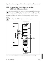
Cable designations
Ê
If no disk array controller is installed, install a supplementary SCSI controller
in a standard slot (see section “Boards in PCI slots” on page 81), disconnect
the SCSI cable for the CD-ROM drive from the SCSI A connector on the
system board, and connect it with the corresponding connector of the new
SCSI controller.
Ê
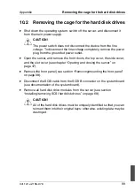
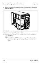
Carefully insert 1/3 of the cage for the hard disk drives into the cage guides,
ensuring that the guides correctly align.
Ê
Thread the two cables through the opening in the separation wall of the
server, and route them to the system board.
Ê
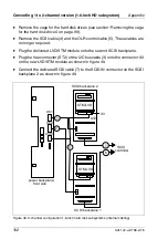
Reach through the CD drive cage aperture, and connect the power cables
to the corresponding connectors X61 and X62, and the I2C bus data cable
to the connector X130 (see figure 49 on page 102) on the power backplane.
Ê
Connect the two SCSI cables to the corresponding connectors (SCSI A and
SCSI B) on the system board or the disk array controller. Refer to the
documentation of the system board for assistance.
Ê
Remount the cage for the accessible drives (CD) (see section “Accessible
drives” on page 75).
Ê
Reinsert the hard disk drive modules, remount all housing components, and
close the server as described in chapter “Opening and closing the server”
on page 47.
No.
Description
1, 2
DC Power
3
I2C bus
6, 7
SCSI long (100 cm)
Summary of Contents for PRIMERGY H200
Page 4: ......
Page 5: ...Related publications and index ...
Page 6: ......
Page 10: ......
Page 18: ...8 U41147 J Z156 2 76 Technical data Introduction ...
Page 19: ...U41147 J Z156 2 76 9 Introduction Technical data ...
Page 20: ......
Page 21: ...U41147 J Z156 2 76 11 Introduction Technical data ...
Page 22: ...12 U41147 J Z156 2 76 Technical data Introduction ...
Page 32: ......
Page 71: ...U41147 J Z156 2 76 61 Troubleshooting and tips Error messages on the control panel ...
Page 72: ......
Page 100: ......
Page 140: ......
Page 142: ......
Page 150: ......
Page 152: ......
Page 154: ......

