U41147-J-Z156-2-76
123
Appendix
Installing/removing the floppy disk drive
Ê
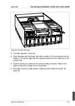
Attach the floor stands using the fastening screws (1). Stand up the server
by turning it 90° to the left. The hard disk drives should then be located verti-
cally on the right side.
Ê
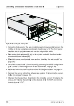
Mount the fastening for the side covers on the housing top.
Ê
Mount the side covers, the top cover, and the front doors (see chapter
“Opening and closing the server” on page 47).
Ê
Mount the front panel (see section “Removing/mounting the front panel” on
page 98).
Ê
Change the chassis ID as described in the section “Changing the chassis ID”
on page 119. Modify the settings for the chassis ID to “H200F” and for the
chassis type to “11H”.
10.9
Installing/removing the floppy disk drive
V
CAUTION!
A few preparatory steps are necessary before you can change the floppy
disk drive, since this drive is not directly accessible from the front.
The floppy disk drive is housed together with the control panel in a drive
carrier.
Ê
Shut down the operating system.
Ê
Switch off the server, and disconnect it from the mains power supply.
V
CAUTION!
The power switch does not disconnect the device from the line
voltage. To disconnect the line voltage completely, remove the power
plug from the grounded power outlet.
Ê
Unlock the server (floorstand model only) (see chapter “Opening and closing
the server” on page 47).
Ê
Take off the front doors (floorstand model only) (see chapter “Opening and
closing the server” on page 47).
Ê
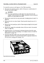
Remove the top cover, the side cover, and the slot cover (see chapter
“Opening and closing the server” on page 47).
Ê
Remove the front panel (see section “Removing/mounting the front panel”
on page 98).
Summary of Contents for PRIMERGY H200
Page 4: ......
Page 5: ...Related publications and index ...
Page 6: ......
Page 10: ......
Page 18: ...8 U41147 J Z156 2 76 Technical data Introduction ...
Page 19: ...U41147 J Z156 2 76 9 Introduction Technical data ...
Page 20: ......
Page 21: ...U41147 J Z156 2 76 11 Introduction Technical data ...
Page 22: ...12 U41147 J Z156 2 76 Technical data Introduction ...
Page 32: ......
Page 71: ...U41147 J Z156 2 76 61 Troubleshooting and tips Error messages on the control panel ...
Page 72: ......
Page 100: ......
Page 140: ......
Page 142: ......
Page 150: ......
Page 152: ......
Page 154: ......

