U41147-J-Z156-2-76
127
Appendix
Mounting/removing the chipcard reader
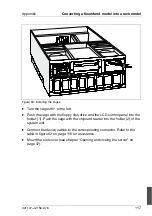
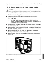
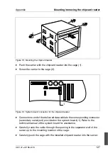
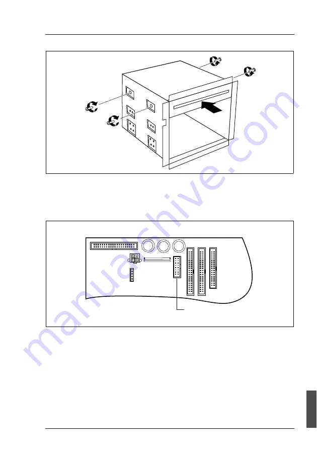
Figure 73: Mounting the chipcard reader
Ê
Push the carrier with the chipcard reader into the cage (1).
Ê
Screw the carrier to the cage (2).
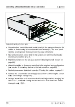
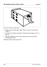
Figure 74: System board: connector for the chipcard reader
Ê
Connect one end of the delivered data cable to the corresponding connector
(secondary serial port) provided on the system board (1). Refer to the
technical manual of the system board for assistance.
Ê
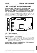
Carefully route the cable through the opening in the separator wall of the
server up to the mounting location of the cage.
Ê
Carefully push the cage with the installed chipcard reader into the server.
1
2
2
2
2
1
Summary of Contents for PRIMERGY H200
Page 4: ......
Page 5: ...Related publications and index ...
Page 6: ......
Page 10: ......
Page 18: ...8 U41147 J Z156 2 76 Technical data Introduction ...
Page 19: ...U41147 J Z156 2 76 9 Introduction Technical data ...
Page 20: ......
Page 21: ...U41147 J Z156 2 76 11 Introduction Technical data ...
Page 22: ...12 U41147 J Z156 2 76 Technical data Introduction ...
Page 32: ......
Page 71: ...U41147 J Z156 2 76 61 Troubleshooting and tips Error messages on the control panel ...
Page 72: ......
Page 100: ......
Page 140: ......
Page 142: ......
Page 150: ......
Page 152: ......
Page 154: ......

