U41147-J-Z156-2-76
29
Installation
Connecting devices to the rack model
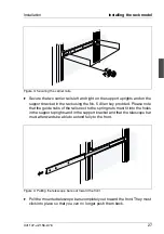
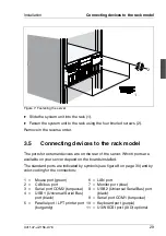
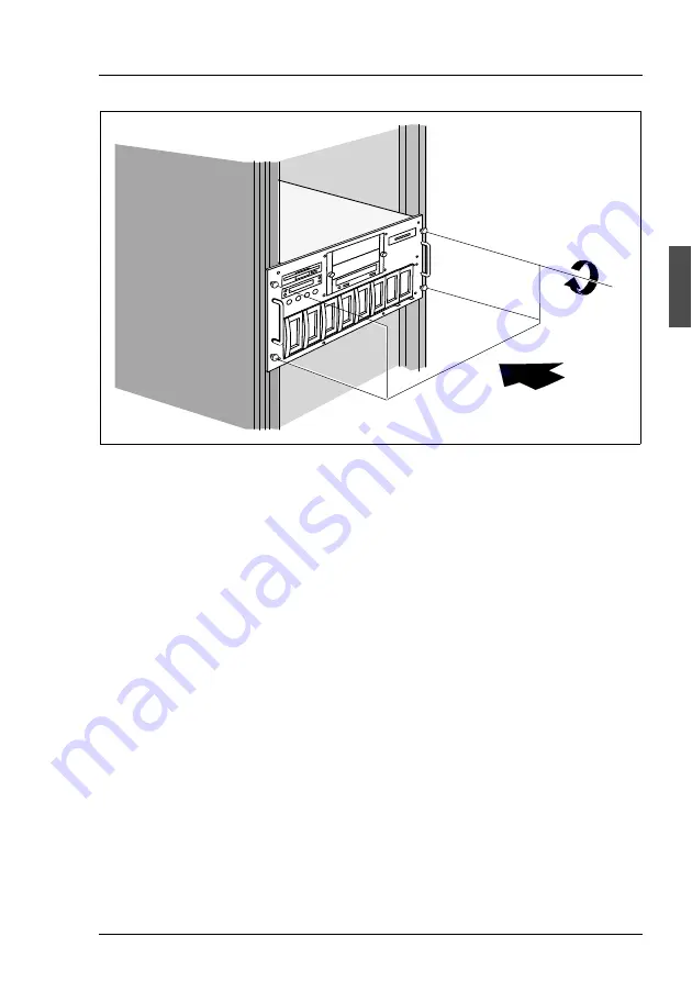
Figure 7: Fastening the server
Ê
Slide the system unit into the rack (1).
Ê
Fasten the system unit to the rack using the four knurled screws (2).
Remove in the reverse order.
3.5
Connecting devices to the rack model
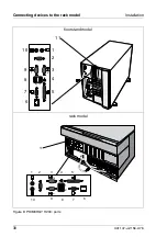
The ports for external devices are on the rear of the server. Which ports are
available on your server depend on the boards installed.
The standard ports are indicated by symbols (see figure 8 on page 30) and by
color-coding for the connectors:
1 = Mouse port (green)
2 = CAN bus port
3 = Serial port COM2 (turquoise)
4 = USB 1 (Universal Serial Bus)
port (black)
5 = Parallel port / LPT printer port
(burgundy)
6 = LAN port
7 = Monitor port (blue)
8 = USB 2 (Universal Serial Bus) port
(black)
9 = Serial port COM1 (turquoise)
10 = Keyboard port (purple)
11 = U3W SCSI port (LVD) optional
1
2
Summary of Contents for PRIMERGY H200
Page 4: ......
Page 5: ...Related publications and index ...
Page 6: ......
Page 10: ......
Page 18: ...8 U41147 J Z156 2 76 Technical data Introduction ...
Page 19: ...U41147 J Z156 2 76 9 Introduction Technical data ...
Page 20: ......
Page 21: ...U41147 J Z156 2 76 11 Introduction Technical data ...
Page 22: ...12 U41147 J Z156 2 76 Technical data Introduction ...
Page 32: ......
Page 71: ...U41147 J Z156 2 76 61 Troubleshooting and tips Error messages on the control panel ...
Page 72: ......
Page 100: ......
Page 140: ......
Page 142: ......
Page 150: ......
Page 152: ......
Page 154: ......

