68
U41147-J-Z156-2-76
SCSI hard disk subsystem
System components and expansions
8.1.3
Swapping SCSI hard disk drives during operation
A SCSI hard disk drive only can be swapped during operation when the orange
hard disk drive error indicator on the hard disk drive module lights up constantly.
V
CAUTION!
Never pull out an hard disk drive module during operation if you are not
sure that the hard disk drive operates on a RAID controller and is part of
a disk array that operates in RAID level 1 or 5.
If you want to swap a SCSI hard disk drive during operation, proceed as follows:
Ê
Pull out the hard disk drive module indicated as defective a few centimeters.
Ê
Wait at least 60 seconds so that the RAID controller can recognize that a
hard disk drive has been removed and also so that the hard disk drive can
come to rest.
Ê
Pull the hard disk drive module completely out.
Ê
Insert the new hard disk drive module.
The SCSI IDs of the hard disk drive modules are permanently assigned (see
also section “1.6-inch hard disk subsystems” on page 91 and section “1-inch
hard disk subsystems” on page 94).
8.1.4
Installing/removing SCSI hard disk drives
The hard disk drives which can be ordered for the server are supplied already
mounted in the hard disk drive carrier. A hard disk drive in the hard disk drive
carrier can only be replaced by a service technician.
If you wish to insert a hard disk drive in an empty hard disk drive bay, then the
dummy cover/module must be removed from this bay beforehand.
Ê
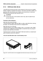
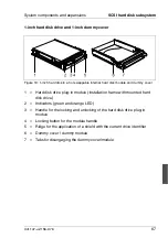
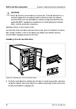
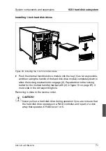
To remove the dummy cover/module, press the two tabs on the left and right
of the dummy cover/module (see folowing figures) together (1) until the
locking mechanism disengages, and pull the dummy cover/module out of
the bay (2).
Summary of Contents for PRIMERGY H200
Page 4: ......
Page 5: ...Related publications and index ...
Page 6: ......
Page 10: ......
Page 18: ...8 U41147 J Z156 2 76 Technical data Introduction ...
Page 19: ...U41147 J Z156 2 76 9 Introduction Technical data ...
Page 20: ......
Page 21: ...U41147 J Z156 2 76 11 Introduction Technical data ...
Page 22: ...12 U41147 J Z156 2 76 Technical data Introduction ...
Page 32: ......
Page 71: ...U41147 J Z156 2 76 61 Troubleshooting and tips Error messages on the control panel ...
Page 72: ......
Page 100: ......
Page 140: ......
Page 142: ......
Page 150: ......
Page 152: ......
Page 154: ......

