86
U41147-J-Z156-2-76
Power supply units
System components and expansions
Ê
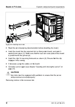
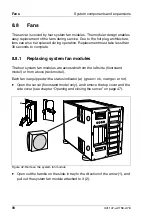
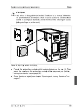
Insert the ventilation system cover, push it forward, and fasten it with the
knurled screw (1).
Ê
Close the server again (see chapter “Opening and closing the server” on
page 47).
8.7
Power supply units
The server can be equipped with up to three power supply units. As a standard,
servers are delivered with one power supply unit. This power supply unit is suffi-
cient for the following server configuration:
–
up to four hard disk drives with 1.6-inch hard disk subsystem
–
up to six hard disk drives with 1-inch hard disk subsystem
–
all controllers (restriction: up to two 3-channel or 4-channel disk array
controllers)
–
4 GB memory
–
two processors
An additional power supply unit is required for servers with more than two RAID
controllers or more than four or six disk drives, depending on the configuration.
A redundant power supply can be set up with two or three power supply units.
If one unit fails, the remaining power supply units ensure unimpaired further
operation. The defective power supply unit can be replaced during operation
(hot plug power supply unit).
V
CAUTION!
Only power supply units of the same type may be mounted.
I
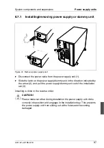
If you want to install, remove, or change a power supply unit on the rack
model, you must first unlock the joint of the articulated cable guide (see
section “Installing the rack model” on page 26) so that the articulated
cable guide can be folded away (figure 9 on page 31).
Once you have exchanged, installed, or removed a power supply unit,
you can fold back the articulated cable guide. The springs of the joint lock
automatically.
Summary of Contents for PRIMERGY H200
Page 4: ......
Page 5: ...Related publications and index ...
Page 6: ......
Page 10: ......
Page 18: ...8 U41147 J Z156 2 76 Technical data Introduction ...
Page 19: ...U41147 J Z156 2 76 9 Introduction Technical data ...
Page 20: ......
Page 21: ...U41147 J Z156 2 76 11 Introduction Technical data ...
Page 22: ...12 U41147 J Z156 2 76 Technical data Introduction ...
Page 32: ......
Page 71: ...U41147 J Z156 2 76 61 Troubleshooting and tips Error messages on the control panel ...
Page 72: ......
Page 100: ......
Page 140: ......
Page 142: ......
Page 150: ......
Page 152: ......
Page 154: ......

