64
U41147-J-Z156-2-76
SCSI hard disk subsystem
System components and expansions
8.1
SCSI hard disk subsystem
The SCSI hard disk subsystem is available in two variants: the 1.6-inch and the
1-inch. It consists of the internal hard disk drive modules, the SCSI backplane,
and the SCSI controller.
You can mount up to 8 hard disk drive modules in PRIMERGY H200 servers
with the 1.6-inch hard disk subsystem and up to 12 hard disk drive modules in
PRIMERGY H200 servers with the 1-inch hard disk subsystem.
The SCSI hard disk subsystem employs Ultra3 SCSI drives (LVD) with a
3½-inch format, a SCA interface, and a maximum height of 1.6 inches and 1
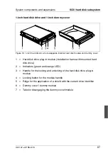
inch, respectively. The hard disk drives are mounted in hard disk drive carriers
with which the hard disk drives can simply be inserted or pulled out. The internal
hard disk drive modules are equipped with a hard disk drive status indicator and
a hard disk drive error indicator.
If a SCSI hard disk drive is operated on a RAID controller and belongs to a disk
array operated with RAID level 1 or level 5, the hard disk drive can be swapped
during operation (hot swapping). To swap a hard disk drive, you need a hard
disk drive with the same or higher capacity. A rebuild on the new hard disk drive
is performed automatically after the swap, provided the RAID controller is
correctly configured. Refer to the information in the manual for the RAID
controller.
So that the storage capacity of the hard disk drive can be recognized at a glance
when the hard disk drive is replaced, several prefabricated stickers with the
storage capacities are provided with the server. Each internal hard disk drive
module should bear a sticker indicating its capacity on the front. Should no
suitable sticker be available, blank stickers for labeling are also provided. The
stickers are color-coded for easier identification.
Summary of Contents for PRIMERGY H200
Page 4: ......
Page 5: ...Related publications and index ...
Page 6: ......
Page 10: ......
Page 18: ...8 U41147 J Z156 2 76 Technical data Introduction ...
Page 19: ...U41147 J Z156 2 76 9 Introduction Technical data ...
Page 20: ......
Page 21: ...U41147 J Z156 2 76 11 Introduction Technical data ...
Page 22: ...12 U41147 J Z156 2 76 Technical data Introduction ...
Page 32: ......
Page 71: ...U41147 J Z156 2 76 61 Troubleshooting and tips Error messages on the control panel ...
Page 72: ......
Page 100: ......
Page 140: ......
Page 142: ......
Page 150: ......
Page 152: ......
Page 154: ......

