


U41147-J-Z156-2-76
75
System components and expansions
Accessible drives
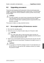
8.3
Accessible drives
The PRIMERGY H200 servers offer a total of four mounting locations for acces-
sible drives:
–
1 x 3½-inch, used by the floppy disk drive
–
3 x 5¼-inch, one of which is used by the CD-ROM drive.
The two free 5¼-inch mounting locations can accept one full-height or two half-
height backup drives (magnetic tape drives).
The floppy disk drive is housed together with the control panel in a cage.
The three 5¼-inch mounting locations are also housed in a cage. The acces-
sible 5¼-inch drives mounted in this cage are warm swappable. Warm
swappable means that the accessible 5¼-inch drives can be replaced while the
server is running; however, for this to work you need an operating system
function that will stop the SCSI bus before you replace the accessible 5¼-inch
drive.
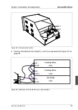
Each accessible 5¼-inch drive must be assigned a unique SCSI ID (4 - 6). The
termination must be switched off. The SCSI bus (8 bit) is terminated on the
backplane with an active terminator; the SCSI bus (16 bit) is terminated on the
SCSI cable.
Ê
Please read the drive documentation.
Ê
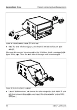
Assign an as yet unassigned SCSI ID to the new accessible 5¼-inch drive,
and disable the terminating resistor.
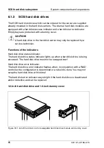
8.3.1
Installing/removing an accessible 5¼-inch drive
Ê
Shut down the operating system.
Ê
Switch off the server, and disconnect it from the main power supply.
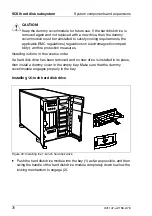
V
CAUTION!
The power switch does not disconnect the device from the line
voltage. To disconnect the line voltage completely, remove the power
plug from the grounded power outlet.
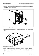
Ê
Unlock the server (floorstand model only) (see chapter “Opening and closing
the server” on page 47).
Summary of Contents for PRIMERGY H200
Page 4: ......
Page 5: ...Related publications and index ...
Page 6: ......
Page 10: ......
Page 18: ...8 U41147 J Z156 2 76 Technical data Introduction ...
Page 19: ...U41147 J Z156 2 76 9 Introduction Technical data ...
Page 20: ......
Page 21: ...U41147 J Z156 2 76 11 Introduction Technical data ...
Page 22: ...12 U41147 J Z156 2 76 Technical data Introduction ...
Page 32: ......
Page 71: ...U41147 J Z156 2 76 61 Troubleshooting and tips Error messages on the control panel ...
Page 72: ......
Page 100: ......
Page 140: ......
Page 142: ......
Page 150: ......
Page 152: ......
Page 154: ......