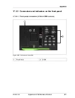
RX2520 M1
Upgrade and Maintenance Manual
417
Appendix
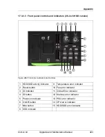
17.3.1.2 Onboard indicators and controls
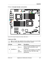
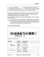
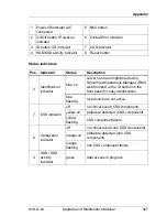
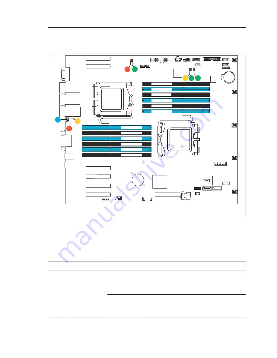
Figure 291: Onboard indicators and Indicate CSS button
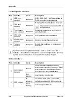
Component LEDs
I
LEDs A, B and C are visible from the outside on the server rear. All other
LEDs are only visible if the top cover has been opened.
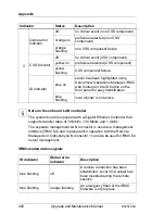
Indicator Status
Description
A
Identification
blue on
server has been highlighted using the ID
button on the front panel for easy
identification
blue
flashing
server has been highlighted using IRMC
(AVR) when local VGA off for easy
identification
CPU 1
CPU 2
external connectors
Management
LAN
LAN 2
Shared LAN
CPU 2 DIMM 1D
CPU 2 DIMM 2D
CPU 2 DIMM 2F
CPU 2 DIMM 1F
CPU 2 DIMM 2E
CPU 2 DIMM 1E
CPU 1 DIMM 1A
CPU 1 DIMM 2A
CPU 1 DIMM 2B
CPU 1 DIMM 1C
CPU 1 DIMM 1B
CPU 1 DIMM 2C
VGA
Serial 1
SKU Key
FAN 1
FAN 4
FAN 2
TPM
1
SATA 1 SATA 2
USB INT2
USB INT1
HDD LED
PWR
HDD/ODD2
PWR
HDD/ODD1
Front Panel
PCH
iRMC
Slot 2 PCIe x8
(mech. x8)
Slot 3 PCIe x8
(mech. x8)
Slot 1 PCIe x4
(mech. x8)
Slot 4*
PCIe
x8
(mech. x8)
Slot 5* PCIe x8
(mech. x8)
Slot 6*
PCIe
x8
(mech. x8)
Slot 7 PCIe x8
(mech. x8)
FAN 3
Battery
SAS 1-4
UFM
USB
stick
SMB 4
PWR
Front VGA
PWR CTRL
Buzzer
USB
1/2
USB
3/4
LAN 1 /
iRMC
micro
SSD
BIOS
BIOS-WP
JP8
JP1
SMB 1
Frontpanel
C
A
B
I
K
F
G
H
Summary of Contents for PRIMERGY RX2520 M1
Page 36: ...36 Upgrade and Maintenance Manual RX2520 M1 Before you start ...
Page 120: ...120 Upgrade and Maintenance Manual RX2520 M1 Power supply units ...
Page 162: ...162 Upgrade and Maintenance Manual RX2520 M1 Hard disk drives solid state drives ...
Page 220: ...220 Upgrade and Maintenance Manual RX2520 M1 Expansion cards and backup units ...
Page 230: ...230 Upgrade and Maintenance Manual RX2520 M1 Main memory ...
Page 310: ...310 Upgrade and Maintenance Manual RX2520 M1 Accessible drives ...
Page 410: ...410 Upgrade and Maintenance Manual RX2520 M1 Cables ...

