504
Upgrade and Maintenance Manual
RX2540 M2
Front panel and external front connectors
13.8.3.6 Concluding steps
Ê
"Installing the fan box" on page 399
Ê
Ê
"Connecting the power cord" on page 79
Ê
"Switching on the server" on page 82
Ê
"Resuming BitLocker functionality" on page 120
13.9 Front panel module on rack mounting
bracket
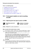
13.9.1 Replacing the front panel module on RMB
Note on system information backup / restore
I
The front panel module contains the Chassis ID EPROM that contains
system information like server name and model, housing type, serial
number and manufacturing data.
To avoid the loss of non-default settings when replacing the system
board, a backup copy of important system configuration data is
automatically stored from the system board NVRAM to the Chassis ID
EPROM. After replacing the system board the backup data is restored
from the Chassis ID board to the new system board.
V
CAUTION!
For that reason the front panel module and system board must not be
replaced simultaneously! In this case, restoring the system configuration
data on the system board would fail.
Field Replaceable Unit
(FRU)
Hardware: 10 minutes
Software: 5 minutes
Tools:
Phillips PH1 / (+) No. 1screw driver
Summary of Contents for PRIMERGY RX2540 M2
Page 6: ...Upgrade and Maintenance Manual RX2540 M2 ...
Page 48: ...48 Upgrade and Maintenance Manual RX2540 M2 Before you start ...
Page 128: ...128 Upgrade and Maintenance Manual RX2540 M2 Basic software procedures ...
Page 142: ...142 Upgrade and Maintenance Manual RX2540 M2 Power supply unit PSU ...
Page 392: ...392 Upgrade and Maintenance Manual RX2540 M2 Processor CPU ...
Page 452: ...452 Upgrade and Maintenance Manual RX2540 M2 Accessible drives ...
Page 558: ...558 Upgrade and Maintenance Manual RX2540 M2 System board and components ...
Page 602: ...602 Upgrade and Maintenance Manual RX2540 M2 Appendix ...

