RX2540 M4
Upgrade and Maintenance Manual
509
System board and components
Ê
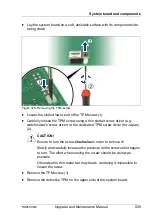
Lay the system board on a soft, antistatic surface with its component side
facing down.
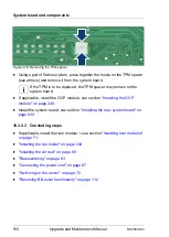
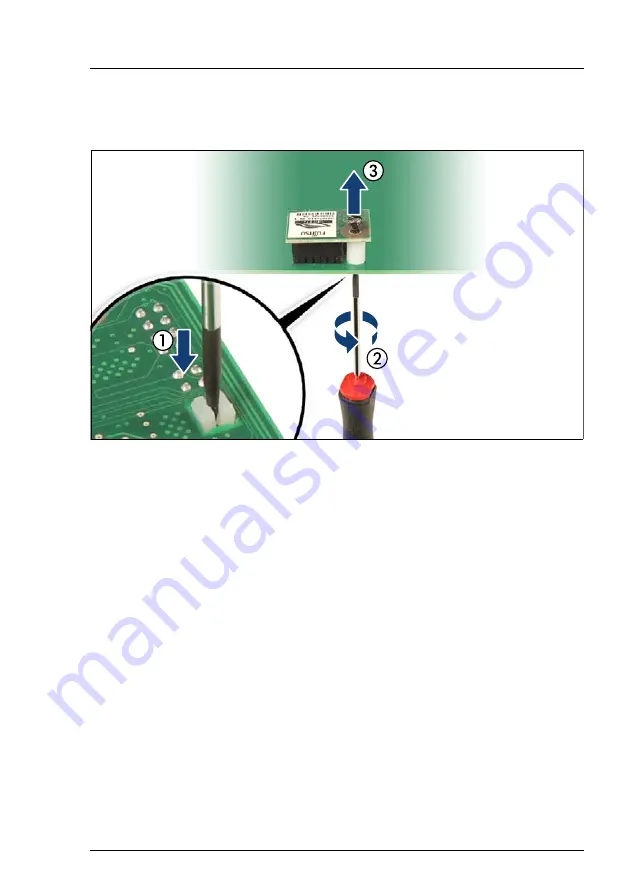
Figure 378: Removing the TPM screw
Ê
Locate the slotted lower end of the TPM screw (1).
Ê
Carefully loosen the TPM screw using a thin slotted screw driver (e.g.
watchmaker's screw driver) or the dedicated TPM screw driver (for Japan)
(2).
V
CAUTION!
Ensure to turn the screw
clockwise
in order to remove it!
Slowly and carefully increase the pressure on the screw until it begins
to turn. The effort when loosing the screw should be as low as
possible.
Otherwise the thin metal bar may break, rendering it impossible to
loosen the screw.
Ê
Remove the TPM screw (3).
Ê
Remove the defective TPM on the upper side of the system board.
Summary of Contents for PRIMERGY RX2540 M4
Page 40: ...40 Upgrade and Maintenance Manual RX2540 M4 Before you start ...
Page 90: ...90 Upgrade and Maintenance Manual RX2540 M4 Basic hardware procedures ...
Page 136: ...136 Upgrade and Maintenance Manual RX2540 M4 Power supply unit PSU ...
Page 228: ...228 Upgrade and Maintenance Manual RX2540 M4 Hard disk drives HDD and solid state drives SSD ...
Page 344: ...344 Upgrade and Maintenance Manual RX2540 M4 Main memory ...
Page 362: ...362 Upgrade and Maintenance Manual RX2540 M4 Processor CPU ...
Page 390: ...390 Upgrade and Maintenance Manual RX2540 M4 Liquid cooling LC ...
Page 498: ...498 Upgrade and Maintenance Manual RX2540 M4 Additional interfaces ...
Page 572: ...572 Upgrade and Maintenance Manual RX2540 M4 Appendix A ...
Page 574: ...574 Upgrade and Maintenance Manual RX2540 M4 Appendix B ...
Page 582: ...8 RX2540 M4 Basic Serial RS 232 Cable plan System Board D3384 RS 232 onboard RS 232 rear C6 ...
Page 634: ...List of all used screws for PRIMERGY Servers Assembled in Germany and Japan January 2017 ...

