background image

241

PRIMERGY RX600 S2 User’s Guide

8

Con

figurin

g Hardwa

re

 a

nd utili

ties

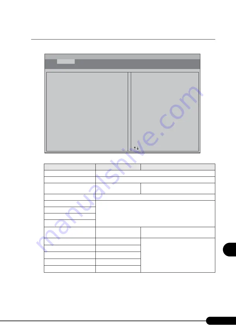
8.3.3 Processor Menu

The CPU information is displayed on the [Processor] menu, and you can change the settings here.

table: Items on the Processor Menu

Item

Settings

Description

Core Frequency

The frequency of installed CPU is displayed.

Bus Frequency

The FSB of installed CPU is displayed.

Processor Retest

• Enabled

• Disabled

initial value

Boot Processor Number

The boot processor number is displayed.

Processor #1 Information

The CPU information is displayed. Select the number of the processor you 

want to check, and press the [Enter] key to display "

 Processor #1 to 4 

Information Screen" (

pg.242) where the detailed information on installed 

CPU is displayed. 

Processor #2 Information

Processor #3 Information

Processor #4 Information

Hyper-Threading Enable

• Enabled

initial value

• Disabled

Set whether or not to enable the hyper-
threading function.

Speed Step (TM)

Auto

unchangeable

These are CPU internal settings.

Execute Disable Bit

Enabled

unchangeable

Hardware Prefetcher

Enabled

unchangeable

Adj. Cache Line Prefetch

Enabled

unchangeable

Enhanced Halt State

Enabled

unchangeable

BIOS SETUP UTILITY

Processor

Main    

Processor

    Memory    Devices    Server    Security    Save, Restore & Exit

Examine and set system Processor parameters.

Core Frequency

Bus Frequency
Processor Retest

Boot Processor Number
> Processor #1 Information
> Processor #2 Information
> Processor #3 Information
> Processor #4 Information

Hyper-Threading Enable
Speed Step (TM)
Execute Disable Bit
Hardware Prefetcher
Adj. Cache Line Prefetch
Enhanced Halt State

3.16GHz

667MHz
<Disabled>

Processor #1

<Enabled>
<Auto>
<Enabled>
<Enabled>
<Enabled>
<Enabled>

Frequency at which processors currently
run.

Esc = Exit
       = Move Highlight

Summary of Contents for Primergy RX600 S2

Page 1: ...plains how to install the OS without using ServerStart Chapter 5 Operations after OS Installation This chapter explains the operations to perform after OS installation Be sure to perform those operations before operating the server Chapter 6 High Reliability Tools For stable PRIMERGY server operations we recommend that high reliability tools be installed This chapter explains the installation and ...

Page 2: ...ic software and application software perform backup and other necessary operations Note that data protection is not guaranteed when repairs are performed It is the customer s responsibility to maintain backup copies in advance In case of data loss Fujitsu assumes no liability for data maintenance or restoration and damages that occur as a result of the data loss for any reason except for items cov...

Page 3: ...e key once When using Windows or DOS OS commands are not case sensitive CD ROM drive names are shown as CD ROM drive Enter your drive name according to your environment CD ROM drive setup exe Ignoring this symbol could be potentially lethal Ignoring this symbol may lead to physical injury and or damage the server or internal options The triangle mark emphasizes the urgency of the WARNING and CAUTI...

Page 4: ...dows Server 2003 Standard Edition Windows Server 2003 Windows Microsoft Windows Server 2003 Enterprise Edition Windows Server 2003 Enterprise Edition Microsoft Windows Server 2003 Standard x64 Edition Windows Server 2003 x64 Microsoft Windows Server 2003 Enterprise x64 Edition Microsoft Windows 2000 Server Windows 2000 Server Microsoft Windows 2000 Advanced Server Windows 2000 Advanced Microsoft W...

Page 5: ... file in the root directory on the ServerStart CD ROM Use a text editor to read it Latest Information about Software Provided with This Server For the latest information regarding ServerStart and other software provided with this server refer to the Fujitsu PRIMERGY website http primergy fujitsu com Warning and Caution Labels Warning and caution labels are found on the server Do not remove or stai...

Page 6: ...6 ...

Page 7: ...1 5 Workflow 42 Chapter 2 Checking befor OS Installation 2 1 Preparation on the Server 44 2 1 1 Installing Internal and External Options 44 2 1 2 Hardware Settings 46 2 2 Selecting the Installation Method 48 2 3 Precautions on Installation 49 2 3 1 Installation Partition Size 49 2 3 2 Notes on Configuring RAID 50 2 3 3 Notes on a Multiple LAN Adapter Configuration 50 2 3 4 Cautions for Using Serve...

Page 8: ...3 4 4 Preparation of Remote Resources 98 3 4 5 Starting Remote Installation Using a PXE Server 99 3 4 6 Starting Remote Installation Using a Remote Resource Server 102 3 5 Installation on Multiple the Second and Subsequent Servers 106 3 5 1 Preparation for Installation 106 3 5 2 Installation in Guided Mode 107 3 5 3 Installation in Preconfiguration Mode 108 Chapter 4 Manual OS Installation 4 1 Cre...

Page 9: ...ert Mode 152 5 5 4 Notes on Advanced Uninterruptible Power Supply UPS 153 5 5 5 Turning the Power On via a LAN 155 5 5 6 Other Notes on Operation 155 5 6 LAN Driver Advanced Setup BACS 157 5 6 1 BACS Installation 157 5 6 2 Load Balance 159 5 6 3 VLAN Setup Procedure 162 5 6 4 Cautions on Using the Teaming SLB Auto Fallback Disable Function 163 5 7 LAN Driver Advanced Setup Intel PROSet 165 5 7 1 I...

Page 10: ...06 7 5 3 How to Install Expansion Cards 210 7 5 4 How to Replace Expansion Cards in the Hot Swappable PCI Slots 212 7 6 Installing Internal Hard Disk Units 214 7 6 1 Where to Install Internal Hard Disk Units 214 7 6 2 Installable Internal Hard Disk Units and Notes 215 7 6 3 How to Install Internal Hard Disk Units 216 7 6 4 How to Remove Internal Hard Disk Units 217 7 6 5 Replacing the Failed Inter...

Page 11: ...ng the Server Condition 254 9 1 2 Cleaning 254 9 2 Troubleshooting 257 9 2 1 Hardware Troubleshooting 257 9 2 2 Error Messages 260 9 2 3 Software Troubleshooting 265 9 3 System Event Log 271 9 3 1 How to Use Server Management Tools 271 9 3 2 Viewing the System Event Log 273 9 3 3 Saving Deleting the System Event Log 273 9 4 Security 275 9 4 1 Hardware Security 275 9 4 2 Security against Unauthoriz...

Page 12: ...pport 285 Appendix A Server Specifications 288 A 1 Diskless Type 288 B Specifications for Internal Options 289 B 1 CPU 289 B 2 Memory 290 B 3 Memory Board 290 B 4 Internal Hard Disk Units 291 B 5 Power Cord Selection 292 C Recycling 294 ...

Page 13: ...is server as well as an overview of the software provided with this server In addition the workflow from placing the server to starting the operation is also described 1 1 RX600 S2 14 1 2 Supplied Software 16 1 3 Component Names and Functions 22 1 4 Standard Operations 30 1 5 Workflow 42 ...

Page 14: ...n the mirror configuration and memory RAID configuration For the disk array configuration a failed hard disk unit in a storage system can be replaced or repaired without turning off the server and peripheral devices a hot plug is supported Hardware and Software Designed for Data Security Locks on the drive covers and the password setting in the BIOS Setup Utility protect hardware and data assets i...

Page 15: ...320 SCSI The Ultra320 SCSI interface which provides a maximum data transfer speed of 320MB sec is supported ensuring high speed data transfer during disk access Excellent Scalability Maximum Memory Size of 32GB In addition to the preinstalled 2GB memory the system has four memory boards One memory board can have four memory cards to support up to 32GB memory Maximum Hard Disk Size of 1500GB Up to ...

Page 16: ...setup Installing ServerStart Not using ServerStart Using ServerStart Setup It is necessary to input successively for installation resulting in more mistakes and longer time Example Operations such as setting IP address creating users and registering computer name are required Auto installation of recommended drivers SCSI LAN etc enables high reliable installation High reliability tools can be inst...

Page 17: ...use any name for the configuration file However the file must be installed in the server as SerStartBatch ini When installing the configuration file make sure to save it as SerStartBatch ini on the ServerStart floppy disk Start up ServerStart insert the ServerStart floppy disk containing SerStartBatch ini and click Start to install the server Intuitive User Interface The intuitive user interface a...

Page 18: ... Clicking a wizard displays a wizard window Set items in the wizard window To move to a step in the next wizard window click the operation button at the bottom of the window Clicking the help button displays a tip for setting the item Brings you to the next page Brings you up one tier Brings you to the main screen Ends ServerStart Changes the size of icons Brings you to the previous page Resets th...

Page 19: ... of files in a short time 1 2 2 High Reliability Tools High reliability tools are a comprehensively useful set of software for stable system operations of the server The following tools have respective roles to manage normal operations or recovery from errors Server monitoring tools System diagnosis support tools LAN driver detailed setting tools Server Monitoring Tools The server monitoring tools...

Page 20: ...0 Server system DSNAP is used for a maintenance engineer to understand your system software configuration and settings correctly and to promote research smoothly Provide this with memory dump to your maintenance engineer LAN Driver Detailed Setting Tools These tools set details on the LAN including the use of the Teaming load balance function and VLAN configuration Intel PROSet Intel PROSet is a t...

Page 21: ...S Installed if selected 1 Will not be installed when a LAN card PG 286 PG 1862 PG 1882 PG 1892 is not installed Linux and Windows Server 2003 x64 do not support batch installation with ServerStart ServerView must be configured after installation even when the high reliability tools have been installed at once with ServerStart Refer to Chapter 6 High Reliability Tools pg 171 RAID Management Tool re...

Page 22: ...nks when data is being read from a CD ROM c CD ROM eject button Press this button to eject a CD ROM Do not press this when the CD ROM access LED is on d LCD panel Indicates system activity and hardware error System activity is usually displayed and when the error occurs the system error is displayed automatically e 5 inch storage bay Contains a 5 inch internal device f Video connector Connects dis...

Page 23: ...D button the front and rear LEDs are lit blue so that the locations of devices being maintained can be determined Also the System Identification LED Display button of ServerView can be used to light them m System ID button When pressing this button the front and rear System ID LEDs are lit blue so that the locations of devices being maintained can be determined n System Power button Press to turn ...

Page 24: ...LED This LED is lit when data is being written to or read from the hard disk When the hard disk is not accessed this is not lit t Hard disk failure LED During an array system configuration this LED is lit amber when an error is detected in the internal hard disk unit It is lit or blinks depending on the hard disk status as follows 1 3 2 Server Rear View a Serial port connector Connects cables of p...

Page 25: ...ED button When pressing this button the front and rear LEDs are lit blue so that the locations of devices being maintained can be determined i System ID LED When pressing the System ID LED button this LED is lit blue so that the locations of devices being maintained can be determined Also the System Identification LED Display button of ServerView can be used to light them table Meaning of the LAN ...

Page 26: ...evice c CPU Socket Installs the CPU Two sockets are installed by default d PCI Slot Contains extension cards that enhance the server functions PCI cards with the PCI bus interface can be installed in the PCI slots e Memory Board Up to four memory modules can be supported This server has one memory board by default and up to four memory boards can be supported a b c d e ...

Page 27: ...ache Memory connector An onboard RAID cache memory is plugged in This is preinstalled e Memory Board Slot Attach the memory board A memory board has two memory banks and can hold a total of four memory modules In this server one memory bank consists of Slots A and B Always install memory modules in pairs f Server Control connector A server control cable is plugged in when a remote service board is...

Page 28: ...l the CPU VRM o VRM connector for CPU3 If you have installed a CPU in CPU Slot 3 install the CPU VRM p VRM connector for CPU3 4 L3 cache The VRM slot for the CPU L3 cache is exclusively used with a CPU of 3 33GHz 8MB For the model with CPUs of 3 33GHz 8MB it is built in 1 3 5 Memory Board a Mirror Configuration LED Green light turns on when the server is in Memory Mirror configuration b RAID Confi...

Page 29: ...the power is not detected on all boards f DIMM Status LED The position of the LEDs corresponds to that of the memory slot This LED is turned off when the DIMM is functioning properly or the memory is not installed Being lit amber indicates error for the corresponding DIMM g Memory Slots Install the memory modules The slots are arranged in the order of Memory Slot 1B Memory Slot 1A Memory Slot 2B a...

Page 30: ...rver on off and inserting ejecting CD ROMs 1 4 1 Opening the Rack Door This section explains how to open the front and rear doors of the 40U standard rack Refer to the manual included with the rack for procedures on opening other rack doors Opening the Front Door 1 Turn the rack key and pull the rack handle up ...

Page 31: ...31 PRIMERGY RX600 S2 User s Guide 1 Overview 2 Turn the handle in the direction of the arrow and pull it forward Opening the Rear Door 1 Turn the rack key and pull the rack handle up Turn and then pull ...

Page 32: ...ard disk in the server and cause data loss Turn the server on when the temperature is in its operating environment range 10 35 C For details about the operating environment refer to Start Guide and Safety Precautions When operating the device outside of this operating environment the server may operate improperly damage data etc Furthermore Fujitsu cannot be held responsible for any related damage...

Page 33: ...ed 9 2 2 Error Messages pg 260 It may take a few seconds until the server is turned on Also when the power cable is connected the server is turned on and off but this is not defective The time to turn on the server can be set with the ASR setting on the Power On Off tab using ServerView supplied with this server For details refer to 3 2 Settings for Server Monitoring in ServerView User s Guide The...

Page 34: ...4 Turn off the display and peripheral devices The time to turn the server off can be set with the ASR setting on the Power On Off tab using ServerView For details refer to 3 2 Settings for Server Monitoring in ServerView User s Guide Follow the procedures below to turn off the server Data can be lost if these procedures are not followed correctly In the event of smoke or sparks immediately unplug ...

Page 35: ...an be specified as the operating mode of the power switch in the OS settings normally Shutdown is specified For Windows 2000 Server Standby Hibernation or Power Off can be specified as the operating mode of the power switch in the OS settings normally Power Off is specified On this server functions corresponding to Standby and Hibernation are supported as BIOS and hardware functions However some d...

Page 36: ...ROMs without the logo Doing so may cause failures Cautions for Handling CD ROMs When removing the disk from the case pull the disk up while pressing the center holder of the case as shown in the figure below Hold the CR ROM on its edge to avoid contact with the disk surface Do not contaminate the CD ROM surface with fingerprints oil or dust If the disk is dirty wipe it from the center to the edge ...

Page 37: ... CD ROM tray comes out a little 2 Pull the CD ROM tray out 3 Place the CD ROM label side up onto the tray While supporting the CD ROM tray push the CD ROM until it clicks into position If the CD ROM is placed improperly when the tray is pushed into the unit the CD ROM or the drive may be damaged Be careful not to touch the lens of the CD ROM drive 4 Move the tray back Push the tray gently until it...

Page 38: ...CD that displays the server status This lets you check the server status on the LCD both when the system is operating normally and when an error occurs and promptly take the necessary action Pulling out the LCD Panel 1 Press the LCD panel gently on the front of the server After the LCD panel has moved forward slightly pull it out towards you 2 Adjust the angle of the LCD panel for a better view LC...

Page 39: ...the first one Types of Information Displayed on the LCD Panel The following types of information are displayed on the screen System Information The current system states such as the server name and the IP address the operating system in use are displayed Error Log Information on the errors that have occurred is displayed An error is displayed in two lines The first line shows a description of the ...

Page 40: ... information error log BIOS POST code Keeps pressing Keeps pressing Keeps pressing Keeps pressing The display is an example is stopped being pressed is stopped being pressed is stopped being pressed is stopped being pressed FUJITSU ROOM21 SERVER 001 System Information Message entries 16 System Information Message 15 of 16 System Time Zone 9 System Information Message 1 of 16 System Location ROOM 2...

Page 41: ...ps pressing Keeps pressing is stopped being pressed is stopped being pressed System Event Log Message entries 40 Power On Self Test Self Test Code F8 FUJITSU System Event Log Message 40 of 40 Proc 2 IERR 27 07 2005 13 16 03 System Event Log Message 1 of 16 Housing open 27 07 2005 10 23 40 OFF by power switch 27 07 2005 21 10 15 ...

Page 42: ...hat ServerStart is used to perform installation Checking precautions on installation Before installing the OS check the precautions on installation by referring to 2 3 Precautions on Installation Procedures before operation Before operating the server refer to Chapter 5 Operations after OS installation High reliability tools installation Start operations Installing internal options Referring to Ch...

Page 43: ...on the server and cautions necessary before OS installation Please read this chapter before starting installation 2 1 Preparation on the Server 44 2 2 Selecting the Installation Method 48 2 3 Precautions on Installation 49 2 4 Preparation for Using ServerStart on a Client Computer 53 ...

Page 44: ...rnal Options pg 177 Options That Must be Installed before the OS installation Memory modules Expansion cards USB floppy disk drive ServerStart floppy disk or driver disk is used to install the OS Connect the USB floppy disk drive in advance Options That Must be Installed after the OS installation Optional SCSI devices Internal hard disk units where the OS is not installed If an internal option dev...

Page 45: ...pplied with the OS The Boot ini file is an important file for the system If the file is edited improperly the system may not start up Edit it carefully Boot ini file description example LAN Cable Be sure to connect the LAN cable when the server is not connected to the Internet If the OS is installed or applications are automatically installed without connecting the LAN cable to the LAN card an err...

Page 46: ...ork startup PXE Also check the MAC address 1 Start the BIOS Setup Utility 2 Select LAN in the Devices menu and press the Enter key The LAN submenu window appears 3 Change Enabled On board NIC ROM to Enabled 4 Check the MAC address shown in the field NIC 1 MAC Address The MAC address is required for remote installation Write it down 5 Press the F10 key to save the current settings and exit the BIOS...

Page 47: ...rver supports onboard SCSI array controller and the array system is configured by default Use the Web BIOS to check or change the array configuration Check or change the configuration as necessary before the OS installation referring to PRIMERGY RX600 S2 Onboard SCSI RAID User s Guide ...

Page 48: ...erverStart pg 16 Installation While Maintaining the Established RAID Environment In guided mode or preconfiguration mode select Use existing array for Configuration Mode at RAID Wizard in the RAID Configuration window and install the OS Installation Using ServerStart While Maintaining the Existing Partitions In expert mode start up Disk Manager format the installation partition and install the OS ...

Page 49: ...ons specify the partition size directly The BOOT partition is the partition for startup Minimum information required for startup such as ntldr is stored The OS partition is the partition for installing the OS In either of the following cases specify a partition size less than 2TB When the same partition is specified as the OS and BOOT partitions When different partitions are specified as the OS an...

Page 50: ...ber of actually installed units is smaller than the setting for the number of units 1 when a hot spare is specified installation using ServerStart is aborted because of an error When the number of installed disk units is greater than the setting the disk units are set up according to the setting Extra units will be configured as standby disk units You can add a physical pack later For more details...

Page 51: ...n be lost Exiting ServerStart After operation in guided or expert mode exiting ServerStart restarts the system Remove disks from the floppy disk and CD ROM drives and click OK When the display on the screen disappears turn off the system License for Use of System for ServerStart License for Use of System for ServerStart linked from the ServerStart startup window is a license for use of Windows PE ...

Page 52: ...llation The partition where the OS is installed must have enough free space for obtaining memory dump For more details refer to 5 1 Memory Dump Paging File Setting pg 134 Cautions on Restarting In the course of installation a message appears to indicate that the setup program restarts Wait until it restarts automatically For background operations refer to PRIMERGY RX600 S2 Onboard SCSI RAID User s...

Page 53: ...as been installed uninstall it The FloppyBuilder function or installation wizard may not operate properly on a different version For details on how to uninstall ServerStart refer to 2 4 2 Uninstalling ServerStart pg 56 1 Insert the ServerStart CD ROM into the client computer The ServerStart Launcher window appears When the ServerStart Launcher window does not appear execute Launcher exe in the CD ...

Page 54: ...indow appears 5 Enter the user information of the software and click Next The Destination Folder window appears 6 Specify the installation folder and click Next To change the installation folder click Browse and select the folder The Select Features window appears 7 Disable ServerStart remote installation and click Next The Ready to Install the Application window appears ...

Page 55: ...ROM is not copied You must click No The ServerStart CD ROM is required to start ServerStart 9 Click Next Installation is executed If a message prompting you to restart the system appears before or after installation eject the CD ROM and restart the system according to the message After restarting the system insert the ServerStart CD ROM and start installation again If the This program does not res...

Page 56: ...rograms on some operating systems 3 Select Fujitsu ServerStart and click Remove or Modify When the uninstallation is executed successfully Fujitsu ServerStart is deleted If ServerStart remote installation has been installed using ServerStart FjPXEServer seems undeleted Leave it and complete the operation On Windows 2000 Professional clients Add or Remove Applications may become unable to respond d...

Page 57: ...Start This chapter explains how to install the OS in the server using ServerStart 3 1 Guided Mode 58 3 2 Preconfiguration Mode 74 3 3 Expert Mode 81 3 4 Remote Installation 88 3 5 Installation on Multiple the Second and Subsequent Servers 106 ...

Page 58: ...the guided mode Please confirm the floppy disk drive of the USB connection has been connected before turning on the power supply of the Server 1 Turn on the server and insert the ServerStart CD ROM immediately ServerStart starts up and a message appears prompting you to insert the ServerStart floppy disk 2 Insert the ServerStart floppy disk supplied with the server Make sure that Removable media a...

Page 59: ...rStart The network setting window for remote installation appears 3 Click OK The Initialization of ServerStart core running window appears and the ServerStart initialization process starts Depending on the hardware configuration this process may take a few minutes ...

Page 60: ...rd language from the drop down list and click OK The subsequent start procedure may take several minutes The Welcome to ServerStart window appears 7 Click Click here to prepare and or initiate an operating system installation The Select the operating system to be installed window appears Click Special Hints on Operating System Installation and read the contents Important information such as limita...

Page 61: ...ode for the selected OS starts up Start up the wizards to set items in the following procedures Exiting the wizard returns the display to the guided mode window Open create configuration file OS installation wizard Application wizard Close save configuration file Starting OS installation RAID wizard Disk wizard connected disks are displayed ...

Page 62: ...omplete configuration file The Open ServerStart Configuration File window appears Once a configuration file is opened another file cannot be opened until you click Close and save Configuration File 2 Select the configuration file and click Create The Create is changed to the Continue 3 Click Continue The RAID Wizard starts up automatically 3 1 3 RAID Wizard pg 63 ...

Page 63: ...yed If you open a configuration file that has been created before displayed settings may differ from the previously set values Be sure to check the settings One hot spare standby disk can be configured When the hot spare disk is set to Yes set the number of disk units to the number of installed disk units minus 1 E g When four hard disk units are installed set the RAID level to RAID5 and when the ...

Page 64: ...ion create a partition on the disks with an active partition and check Erase all existing partitions on all displayed disks The default setting for the controller type is RAID Use this setting 2 Add remove or modify partitions as necessary Partition size of the FAT file system When FAT is selected in File system and a value equal to or more than 4095MB or Auto matic setting is specified in Partiti...

Page 65: ...on is added to the partition list Remove a partition 1 Select the partition to remove and click REMOVE The partition is removed Modify the partition configuration 1 Select the partition to modify and click MODIFY The Disk Configuration window appears 2 Change items and click continue The partition is modified 3 Click leave wizard after settings are completed The disk wizard closes ...

Page 66: ...nding on the OS to be installed The following describes operations on Windows Server 2003 1 Click Operating System Wizard Operating system parameters The Windows Installation window appears 2 Enter the password in Password for Administrator account and Please repeat Password and click Next If the password differs between Password for Administrator account and Please repeat Pass word an error dialo...

Page 67: ...M applied Service Pack 1 on Windows Server 2003 select the OS including SP1 menu from the Operating System Type list The Installation Directory and Time Zone window appears 4 Set items and click Next The User Name window appears 5 Set items and click Next The Display Settings window appears ...

Page 68: ...68 Chapter 3 OS Installation Using ServerStart 6 Set items and click Next The Network Protocol window appears ...

Page 69: ...69 PRIMERGY RX600 S2 User s Guide 3 OS Installation Using ServerStart 7 Set items and click Next The Software Components window appears ...

Page 70: ...70 Chapter 3 OS Installation Using ServerStart 8 Set items and click Next The Services window appears 9 Set items and click leave wizard The OS installation wizard closes ...

Page 71: ...ons such as high reliability tools 1 Click Application Wizard Select additional software components The application wizard appears 2 From the Installable applications list select applications to be installed and click Set all applications to be installed on the Selected applications list 3 Click leave wizard The application wizard closes ...

Page 72: ...n is possible only when it is saved as SerStartBatch ini When installing the OS make sure to save it as Ser StartBatch ini on the ServerStart floppy disk 3 1 8 Start OS Installation Install the OS to the server During installation do not use the mouse or keyboard unless it is necessary for installation operations Otherwise installation may fail 1 Click Click here to Start the Installation of OS Th...

Page 73: ...rStart CD ROM appears 4 Insert the ServerStart CD ROM and click OK The License Agreement window appears 5 Click I agree After files are copied a message prompting you to eject the CD ROM and floppy disk appears 6 Eject the CD ROM and floppy disk and click OK Then the system is restarted The system continues the installation operation after restart OS GUI setup LAN utility installation Service Pack...

Page 74: ...art is started up on a computer where a different version of ServerStart is installed the installation wizard may not operate properly Make sure to uninstall a different version of ServerStart 3 2 1 Starting Up the Preconfiguration Mode Start up the preconfiguration mode 1 Start up ServerStart If ServerStart has already been started it is not necessary to start it up again If it has not start it u...

Page 75: ...d the Floppy disk has been created message appears 5 Click OK 6 Click HOME on the tool bar The display returns to the Welcome to ServerStart window 7 Click Click here to prepare an operating system installation for a PRIMERGY Server The Select an Operating System window appears Before starting installation click Special Hints on Operating system Installation and read the contents Important informa...

Page 76: ...76 Chapter 3 OS Installation Using ServerStart 9 Select the OS to be installed The Preparing the Installation window appears ...

Page 77: ...res refer to description on guided mode wizards 3 1 2 Open create a Configuration File pg 62 to 3 1 6 Application Wizard pg 71 Exiting a wizard returns the display to the preconfiguration mode window Open create configuration file OS installation wizard Application wizard Close save configuration file Starting OS installation RAID wizard Activate ServerStart in the server Disk wizard ...

Page 78: ...t Configuration File window appears 2 Click Save As The ServerStart Session IP Settings window appears 3 Set items when performing remote installation 4 Click Set The configuration file is saved You can specify any name for the configuration file However OS installation is possible only when it is saved as SerStartBatch ini When installing the OS make sure to save it as SerStartBatch ini on the Se...

Page 79: ... the ServerStart floppy disk appears 2 Insert the ServerStart floppy disk containing the created configuration file and click OK Set the ServerStart floppy disk in the write enabled state If it is write protected installation will fail The Initializing ServerStart window appears and the ServerStart initialization process starts Depending on the hardware configuration this process may take a few mi...

Page 80: ...ied a message prompting you to eject the CD ROM and floppy disk appears 7 Eject the CD ROM and floppy disk and click OK The system restarts The system continues the installation operation after restart OS GUI setup LAN utility installation Service Pack installation and Active Directory installation are performed automatically 8 When a confirmation message appears on restart click Restart The syste...

Page 81: ...Start floppy disk supplied with the server Make sure that Removable media and A are selected and click Create The network setting window for remote installation appears Set the ServerStart floppy disk in the write enabled state 3 Click OK The Initialization of ServerStart core running window appears and the ServerStart initialization process starts Depending on the hardware configuration this proc...

Page 82: ...s limitations on disk configuration is described 8 Click MS Windows Operating Systems The Microsoft Windows Operating System Installation window appears 9 Select the OS to install 10 Click Install MS Windows Server 2003 interactively expertise required The expert mode starts Start up the configuration tools to set items in the following procedures Exiting a tool returns to the display to the exper...

Page 83: ...mat the OS installation partition Select the OS installation partition and click the Partition menu Format The Format Partition window appears Be sure to specify the active partition on drive C Partitions equal to or larger than 4096MB cannot be FAT formatted 3 Set items and click Format The partition is formatted 4 When the formatting is completed click the File menu Exit Disk Manager closes and ...

Page 84: ...ick No The Windows Installation window appears 3 Enter the password in Password for Administrator account and Please repeat Password and click Next If the password differs between Password for Administrator account and Please repeat Pass word an error dialog window appears Enter the password correctly The Computer Identification window appears 4 Set items and click Next The Installation Directory ...

Page 85: ...he server When the installation partition is not empty a confirmation message appears If it does not matter click OK to continue the installation procedure If an incorrect setting such as the CD key is found during installation an error window will appear Enter the correct value in the window to continue the installation procedure However corrections made here are not reflected to the configuratio...

Page 86: ...pears insert the CD ROM and click OK 4 When a message prompting you to insert the OS CD ROM appears insert the CD ROM and click OK After files are copied a message prompting you to insert the ServerStart CD ROM appears 5 Insert the ServerStart CD ROM and click OK The License Agreement window appears 6 Click I Agree After files are copied a message prompting you to eject the CD ROM and floppy disk ...

Page 87: ...m Click Start Shutdown Select Restart and click OK The system restarts 11 When the system restarts log on to the server using the Administrator account for the local computer The server setup and OS installation have been completed Refer to Chapter 5 Operations after OS Installation pg 133 and perform necessary procedures before starting server operations ...

Page 88: ...n the network and install them via the network If a remote resource server is configured you can install the same resources to multiple servers This method is useful in configuring multiple servers Target Server and Remote Resource Server PXE Server A server to which resources are installed is called a target server A server that stores resources necessary for remote installation is called a remot...

Page 89: ...you have multiple servers select one for performing the DHCP service and another for storing remote resources Remote Installation Using a Remote Resource Server In remote installation using a remote resource server ServerStart starts up on the target server Procedures for starting installation are the same as those in normal installation preconfiguration guided and expert modes Once installation s...

Page 90: ... remote resource server PXE server and check it for enough free space for storing resources Checking the Number of Servers When you have only one server use it as the remote resource server PXE server and DHCP service server Check it for the required amount of free space When you have multiple servers Check if a server performing the DHCP service exists If not decide a server for the DHCP service ...

Page 91: ...n using a PXE server preparatory procedures such as installing ServerStart are required Perform the following procedures to prepare the PXE server Starting the DHCP Service Check that the DHCP service is running on the same network If the DHCP service function is not installed perform the following procedures for Windows Server 2003 to install the DHCP service 1 Click Start Control Panel Add or Re...

Page 92: ...rStart 1 Insert the ServerStart CD ROM into the PXE server The ServerStart Launcher window appears When the ServerStart Launcher window does not appear execute Launcher exe in the CD ROM 2 Click OK The Windows installer starts and the Setup window appears 3 Click Next The License Agreement window appears 4 Select I accept the license agreement and click Next The User Information window appears 5 E...

Page 93: ...ion folder and click Next To change the installation folder click Browse and select the folder The Select Features window appears Configure ServerStart remote installation so that it will be installed Clicking Disk Cost displays the following widow where you can check the amount of free space ...

Page 94: ...stallation Using ServerStart 7 Click Next The contents tree window appears 8 Configure the ServerStart image necessary for network startup PXE and click Next The Useraccount for access to the content tree window appears ...

Page 95: ...he PXE server performs the DHCP service or select no when the DHCP and PXE servers are configured separately Then click Next The PXE server window appears 11 When there are multiple LAN ports click select select the LAN controller on the LAN controller selection screen and click Next The Important hint window appears 12 Click Next The Ready to Install the Application window appears ...

Page 96: ...e file copying process takes about 10 to 20 minutes The installation completes when the installation completion window appears 15 Click Start Shutdown Select Restart and click OK The system restarts Checking Services Checking PXE Services and TFTP Service 1 Right click the My Computer icon and click Manage 2 Select Services from Services and Applications On the Services list check that PXE Service...

Page 97: ...060 ClassID server option is added Setting TFTP TFTP is an FTP service function that requires no authentication In remote installation the TFTP service is used to distribute the boot image required for startup For the TFTP path set the appropriate access rights for the Guest account to obtain the image via network startup PXE 1 Click Start Programs Accessories Windows Explorer and move to the TFTP...

Page 98: ...er PXE server before starting installation For sharing resources log on to the remote resource PXE server with the Administrator account 1 Prepare resources required for installation CD ROM for the OS to be installed Service Pack CD ROM for the OS to be installed ServerStart floppy disk PRIMERGY Document Tool CD for installing ServerView Others 2 Create a shared folder for storing resources Create...

Page 99: ...re unique information to LAN cards Check the MAC address on each target server Write down the MAC address of the onboard LAN For details on how to check the MAC address of an onboard LAN refer to 2 1 2 Hardware Settings pg 46 Creating a Configuration File You can create a configuration file on a client computer before starting installation For the procedure refer to 3 2 1 Starting Up the Preconfig...

Page 100: ...lick Microsoft Windows Server Operating System Preparing and or initiating a Remote Installation The Microsoft Windows Operating System Installation window appears 4 Click the OS to install The Preparing the Installation window appears If a configuration file has already been created go to Step 6 5 Set items in wizards to create a configuration file Refer to 3 2 2 Configure Settings in Wizards pg ...

Page 101: ...MAC address of target system 2 Select the PRIMERGY model type 3 Specify the Configuration File containing the installation settings 8 Click Start Installation Installation starts All disk contents on the target server are deleted The ServerStart Boot Manager window appears Check that the status is Waiting for client ...

Page 102: ...stallation have been completed Refer to Chapter 5 Operations after OS Installation pg 133 and perform necessary procedures before starting server operations 3 4 6 Starting Remote Installation Using a Remote Resource Server In remote installation using a remote resource server installation is performed using shared resources on the remote resource server Perform 3 4 4 Preparation of Remote Resource...

Page 103: ...ing window appears and the ServerStart initialization process starts Depending on the hardware configuration this process may take a few minutes When the process is completed the Create a ServerStart Floppy Disk window appears 3 Click Build a ServerStart Floppy Disk Creation of a ServerStart floppy disk starts When the creation is completed the Floppy disk has been created message appears When the...

Page 104: ...d click OK The system restarts When the installation is completed an installation completion message appears on the target server 9 Press any key on the target server 10 Restart the system on the target server The server setup and OS installation have been completed Refer to Chapter 5 Operations after OS Installation pg 133 and perform necessary procedures before starting server operations In Prec...

Page 105: ...rver via the network 5 Eject the CD ROM and floppy disk and click OK The system restarts When the installation is completed an installation completion message appears on the target server 6 Press any key on the target server 7 Restart the system on the target server The server setup and OS installation have been completed Refer to Chapter 5 Operations after OS Installation pg 133 and perform neces...

Page 106: ...is installation method will not work 3 5 1 Preparation for Installation Required Software The following software is required for installation on the second and subsequent servers Be sure to have these items close at hand CD ROM for the OS to be installed ServerStart CD ROM ServerStart floppy disk A ServerStart floppy disk containing the configuration file used for installation on the first server ...

Page 107: ... the process is completed the Create a ServerStart Floppy Disk window appears 4 Click or insert a Server Start Floppy Disk to Start Server Start The Welcome to ServerStart window appears 5 Click Click here to prepare and or initiate an operation system installation The Select the operating system to be installed window appears 6 Click MS Windows Operating Systems The Microsoft Windows Operating Sy...

Page 108: ...to follow these installation procedures Performing the procedure in 3 2 1 Starting Up the Preconfiguration Mode pg 74 deletes the contents of the ServerStart floppy disk making the disk unavailable for installation on multiple servers 1 Start up ServerStart If ServerStart has already been started you do not have to restart it If it is not started perform the following startup procedures When the C...

Page 109: ...to the values set on the first server For installation on subse quent servers you must change the following items in the OS installation wizard For other items change the settings as necessary You do not need to start up wizards where no settings will be changed If the settings for the first server are not reflected to wizards perform the procedures from copying the floppy disk over again table Se...

Page 110: ...110 Chapter 3 OS Installation Using ServerStart ...

Page 111: ... Chapter 4 Manual OS Installation This chapter explains how to install the OS without using ServerStart 4 1 Creating Driver Disks 112 4 2 Starting Manual Installation 118 4 3 Installing the LAN Driver 126 ...

Page 112: ...ndows Server 2003 x64 Expansion card onboard controller Driver Chipset Intel E8500 Chipset Driver for Windows 2000 2003 2003 x64 V7 0 0 1019 Graphic controller Standard driver provided with the OS Onboard SCSI array controller PG 142E3 PRIMERGY RX600S2 Onboard RAID Windows 2003 x64 Drivers Disk V4 0L10 1 RAID Ctrl 2 Channel 128MB w BBU PG 142E3 SCSI Ctrl U160 PG 128 Standard driver provided with t...

Page 113: ...er 9 2 1 SCSI Ctrl U160 PG 128 Standard driver provided with the OS Fibre Channel Controller PG FC201 PG FC201 Windows 2000 2003 Drivers Disk V5 20a8 1 SAF TE Driver SAF TE Driver V1 0 0 0 Other expansion cards Driver supplied with the expansion card table Drivers Required for Installing Windows 2000 Server Expansion card onboard controller Driver Chipset Intel E8500 Chipset Driver for Windows 200...

Page 114: ...l the proper version For details on how to uninstall ServerStart refer to 2 4 2 Uninstalling ServerStart pg 56 The FloppyBuilder function may not operate correctly if you start up ServerStart while ServerStart of a different version is installed in the computer Make sure to uninstall a different version of ServerStart ServerStart cannot be started with Windows Server 2003 x64 Please start ServerSt...

Page 115: ...verStart starts up and a message appears prompting you to insert the ServerStart floppy disk 2 Insert the attached ServerStart floppy disk into the server s floppy disk drive Then make sure Removable media and A are selected and click Create A network setup window for remote installation appears If a configuration file already exists in the ServerStart floppy disk and OK is clicked without clickin...

Page 116: ...zation process starts Depending on the hardware configuration this process may take a few minutes When the process is completed the Create a ServerStart Floppy Disk window appears 4 Click or Insert a ServerStart Floppy Disk to Start ServerStart The Welcome to ServerStart window appears 5 Eject the ServerStart floppy disk ...

Page 117: ...00 Server or Windows Server 2003 x64 The FloppyBuilder Driver Disk window appears 3 Click the type of the driver you want to create 4 Click the driver disk you want to create Follow the message and insert a floppy disk 5 Perform the procedures following the messages on the window The floppy disk will be formatted automatically and file copying will start The driver disk is automatically created Wh...

Page 118: ...active area is specified on the hard disk the following message appears Pressing any key while this message is displayed boots the system from the CD ROM 3 The Windows Server 2003 x64 Setup window appears Immediately the following message appears at the bottom of the window Press the F6 key This message will be displayed for a short time after the setup window blue screen appears Press the F6 key ...

Page 119: ...tions in the window to perform installation 4 When the Intel R Chipset Software Installation Utility is complete message appears eject the ServerStart CD ROM from the CD ROM drive and click Finish to restart the system 7 Install the LAN driver Install the LAN driver using the driver disk created from the ServerStart CD ROM For more details refer to 4 3 Installing the LAN Driver pg 126 8 Install th...

Page 120: ...n pg 133 and perform the necessary procedures 4 2 2 Installing Windows Server 2003 1 Create driver disks Prepare necessary drivers before installing Windows Server 2003 Some drivers are created from the ServerStart CD ROM For how to create driver disks refer to 4 1 Creating Driver Disks pg 112 2 Insert the Windows Server 2003 CD ROM Turn on the server and insert the Windows Server 2003 CD ROM imme...

Page 121: ... appears exit ServerStart 2 Execute the following command on the ServerStart CD ROM CD ROM drive DRV ChipSet Intel General W32 infinst_autol exe The installation wizard starts up 3 Click Next Follow instructions in the window to perform installation 4 When the Intel R Chipset Software Installation Utility is complete message appears eject the ServerStart CD ROM from the CD ROM drive and click Fini...

Page 122: ... reliability tools To ensure stable server operation refer to Chapter 6 High Reliability Tools pg 171 and install high reliability tools The installation of Windows Server 2003 has completed Before Starting Operation After OS installation refer to Chapter 5 Operations after OS Installation pg 133 and perform the necessary procedures 4 2 3 Installing Windows 2000 Server 1 Create driver disks Prepar...

Page 123: ...ppy disk appears insert the proper driver disk and press the Enter key Repeat these procedures to install a driver for another card 5 Follow the instructions from the setup program to continue the installation procedures Cautions on Restarting In the course of installation a message appears to indicate that the setup program restarts Wait until it restarts automatically 6 Apply Windows 2000 Servic...

Page 124: ...he displayed menu 3 Click Device Manager from the displayed list 4 Double click TOSHIBA SAF TE SCSI Processor Device under System devices The properties window appears 5 Click the Driver tab and click Update Driver The Upgrade Device Driver Wizard window appears 6 Select Display a list of known drivers for this device so that I can choose a specific and click Next 7 Select FSC SCSI Termination Mod...

Page 125: ... the CD ROM drive and restart the system to make the settings effective 11 Installing high reliability tools To ensure stable server operation refer to Chapter 6 High Reliability Tools pg 171 and install high reliability tools The installation of Windows 2000 Server has completed Before Starting Operation After OS installation refer to Chapter 5 Operations after OS Installation pg 133 and perform ...

Page 126: ...t CD ROM into the server 3 Click Update Driver in the Driver tab window The Welcome to the Hardware Update Wizard window appears 4 Check No not this time and click Next 5 Select Install the software automatically Recommended and click Next The driver will be installed 6 Click Finish 7 Click Close to close the properties window If PG 1862 LAN driver is installed LAN adapter name is changed to Intel...

Page 127: ...mputer Management 2 Click Device Manager On the Device Manager list check if a recognized network adapter is present Window example When a recognized network adapter is present Network adapters appears When a recognized network adapter is present Perform Updating LAN Drivers pg 128 on the LAN device name under Network adapters then Installing the LAN Driver pg 129 on Ethernet controller under Othe...

Page 128: ...d the system is restarted Updating LAN Drivers Perform the following procedures on all LAN device names under Network adapters in Device Manager 1 Double click a LAN device name under Network adapters Names of the LAN devices are displayed as follows 2 Insert the driver disk created from the ServerStart CD ROM into the server 3 Click Update Driver in the Driver tab window The Welcome to the Hardwa...

Page 129: ...eneral tab window The Welcome to the Hardware Update Wizard window appears 4 Select Install the software automatically Recommended and click Next The driver will be installed 5 Click Finish 6 Click Close to close the properties window 7 Remove the driver disk and restart the system After LAN driver installation names of the LAN devices are displayed as follows table LAN device name LAN cards LAN d...

Page 130: ... controller under Other devices The properties window for the Ethernet controller appears 5 Click Reinstall Driver in the General tab window The Device Driver Upgrade Wizard window appears 6 Click Next 7 Select Search for a suitable driver for my device Recommended and click Next The Identify Driver File window appears 8 Select Floppy disk drive in Search location options and click Next Detected d...

Page 131: ...ert the driver disk created from the ServerStart CD ROM and install the driver The Digital signature was not found message may appear If it appears click Yes to con tinue the operations When the Overwriting the Files window appears normally do not overwrite the files select Do not overwrite all files After LAN driver installation names of the LAN devices are displayed as follows 4 3 4 Latest Drive...

Page 132: ...132 Chapter 4 Manual OS Installation ...

Page 133: ...hese operations before operating the server 5 1 Memory Dump Paging File Setting 134 5 2 Creating a Disk for System Recovery 143 5 3 Storing the System Configuration Information 145 5 4 Creating Maintenance Tools 148 5 5 Notes Before Operating the Server 152 5 6 LAN Driver Advanced Setup BACS 157 5 7 LAN Driver Advanced Setup Intel PROSet 165 ...

Page 134: ...rd Disk Free Space To obtain memory dump sufficient hard disk capacity is required for creating paging files and memory dump files The obtainable dump types and required hard disk capacity are as follows Complete Memory Full Dump When the system unexpectedly stops contents of the whole system memory are recorded The file is stored in the directory displayed in the Dump file box Paging file Install...

Page 135: ...y Paging file 2MB or more Memory dump file 64KB or 128KB Memory Dump File Setting Set up the memory dump file according to the following procedures 1 Log on to the server with administrator privileges 2 Check free space of the drive where the memory dump file is to be stored Check the required amount of free space according to Checking Hard Disk Free Space pg 134 If the drive has no free space ref...

Page 136: ...or complete memory dump if Overwrite any existing file is checked debugging information is overwritten to the specified file every time 6 Click OK to close the Startup and Recovery window 7 Click OK to close the System Properties window 8 Restart the system The setting is enabled after the system is restarted Paging File Setting Set up the paging file according to the following procedures 1 Log on...

Page 137: ...dvanced tab 6 Click Change in the Virtual memory section The Virtual Memory window appears 7 Specify the drive where the paging file is to be created In Drive select the drive where the system is installed The selected drive is displayed in Drive in Paging file size for selected drive ...

Page 138: ... specified is displayed in Paging File Size of Drive 11 Click OK to close the Virtual Memory window 12 Click OK to close the Performance Options window 13 Click OK to close the System Properties window 14 Restart the system The setting is enabled after the system is restarted 5 1 2 How to Obtain Memory Dump For Windows 2000 Server Check the following settings before starting configuration to obtai...

Page 139: ...ation for problem identification is recorded In this option a paging file of at least 2MB is required in the boot volume Also a new file is created each time the system unexpectedly stops History of such files is stored in the directory displayed in Small dump directory usually C winnt minidump Included information Common header minidump header kernel module memory information processor informatio...

Page 140: ... Kernel memory dump Only kernel memory is recorded to the memory dump file Complete memory dump Recommended The whole system memory information is recorded to the memory dump file 2 In Dump File or Small dump directory specify the directory to save the memory dump file with its full path In case of kernel memory dump or complete memory dump if Overwrite any existing file is checked debugging infor...

Page 141: ...e space of the drive where the system is installed Check the required amount of free space according to Checking Hard Disk Free Space pg 138 If the drive has no free space refer to Cannot Collect the Memory Dump pg 268 3 Click Start Settings Control Panel 4 Double click the System icon The System Properties window appears 5 Click the Advanced tab and click Performance Options The Performance Optio...

Page 142: ...l paging file size for all drives When a smaller value is specified for the paging file size performance may be affected We recommend to specify the paging file size larger than the recommended value 9 Specify the Maximum size Specify a value larger than the Initial size 10 Save the settings Click Set in the Paging file size for selected drive section The settings are saved and the value specified...

Page 143: ...system recovery set To do this you need an unused formatted floppy disk and a medium to store back up files 1 Click Start All Programs Accessories System Tool Backup The Backup or Recovery Wizard window appears 2 Click Next The Backup or Recovery window appears 3 Select Create a backup of files and settings and then click Next The Items to Create Backups window appears 4 Select All the information...

Page 144: ...en created Store the automated system recovery set just created in a secure location 5 2 2 Creating a System Recovery Disk For Windows 2000 Server After setting up Windows Server 2000 create a system recovery disk To do this you need an unused formatted floppy disk 1 Put a label showing Windows 2000 system recovery disk onto a floppy disk and insert it into the floppy disk drive 2 Click Start Prog...

Page 145: ...nce engineer Preparation for Using Server Management Tools Before using Server Management Tools prepare the Server Management Tools CD ROM and Server Management Tools work FD disk supplied with the server at hand Cautions Server Management Tools are for this server only Do not use those tools on other systems Otherwise the system may be corrupted Only the information that is configured with the BI...

Page 146: ... storing the BIOS information For details of ServerView refer to ServerView User s Guide 1 Turn on the server and insert the Server Management Tools CD ROM into the CD ROM drive and the Server Management Tools work FD disk into the floppy disk drive 2 When the DOS prompt window appears enter the following command and press the Enter key C cd smtool C SMTOOL biossave bat If storing has already been...

Page 147: ...unpredictable at such times as an abrupt power interruption or restart If the server is operated with the OS Boot Monitoring function enabled enable the function again before resuming operation For details of ServerView refer to ServerView User s Guide 1 Turn on the server and insert the Server Management Tools CD ROM into the CD ROM drive and the Server Management Tools work FD disk into the flop...

Page 148: ... make sure to uninstall the ServerStart Then perform installation again For details on how to uninstall ServerStart refer to 2 4 2 Uninstalling ServerStart pg 56 The FloppyBuilder function may not operate correctly if you start up ServerStart while ServerStart of a different version is installed in the computer Make sure to uninstall a different version of ServerStart ServerStart cannot be started...

Page 149: ...window appears When Creating a DOS Floppy Disk on the Server 1 Turn on the server and insert the ServerStart CD ROM immediately after that ServerStart starts up and a message appears prompting you to insert the ServerStart floppy disk 2 Insert the attached ServerStart floppy disk into the server s floppy disk drive Then make sure Removable media and A are selected and click Create A network setup ...

Page 150: ...tialization process starts Depending on the hardware configuration this process may take a few minutes When the process is completed the Create a ServerStart Floppy Disk window appears 4 Click or Insert a ServerStart Floppy Disk to Start ServerStart The Welcome to ServerStart window appears 5 Eject the ServerStart floppy disk ...

Page 151: ... ServerStart FloppyBuilder window appears 2 Click DOS Diskette Insert the prepared floppy disk by following the message 3 Perform the subsequent operations according to the messages on the window The floppy disk will be formatted automatically and file copying will start The DOS floppy disk will be created automatically When a message appears indicating that the disk is created click OK and eject ...

Page 152: ...xecute Windows Update periodically Executing Windows Update requires a network environment connectable to the Internet 5 5 2 Auto run Function from CD ROM Drives Perform the following procedures to change the settings of the auto run function from the CD ROM drives after server installation 1 Make the registry editable and change the value of AutoRun of the following registry key HKEY_LOCAL_MACHIN...

Page 153: ...anage 2 Click Disk Management 3 Right click the partition to change the letter and select Change Drive Letter and Path The Change Drive Letter and Path window appears 4 Click Edit The Change Drive Letter or Path window appears 5 Change the drive letter 5 5 4 Notes on Advanced Uninterruptible Power Supply UPS Note the following points when using an advanced uninterruptible power supply referred to ...

Page 154: ...2003 Linux Set Actions after Power Failure to Restore the server For Windows 2000 Server Set Actions after Power Failure to Restore the state before power failure Configuration Using Server Management Tools 1 Turn on the server and insert the Server Management Tools CD ROM into the CD ROM drive 2 When the DOS prompt window appears enter the following command and press the Enter key C cd smtool C i...

Page 155: ...rt the BIOS Setup Utility 8 3 1 Starting and Exiting the BIOS Setup Utility pg 237 2 Set WOL Resume from S5 of the Server menu to Enabled 3 Press the F10 key The confirmation message whether to save the changes is displayed 4 Select Yes and press the Enter key To start up the server via a LAN refer to Performing Remote Installation pg 46 5 5 6 Other Notes on Operation Unnecessary Files After OS in...

Page 156: ...Chapter 5 Operations after OS Installation Unintentional Power off Prevention We recommend the installation of a special power supply device such as a distribution board to prevent unplanned power shut offs ...

Page 157: ...ps of the onboard LAN Use of Intel PROSet Use Intel PROSet pg 165 to perform the following advanced setups of a LAN card Use the Teaming function between LAN cards or between a LAN card and the onboard LAN Setup a VLAN using a LAN card Use the Jumbo frame with a LAN card Perform the other advanced setups of a LAN card 5 6 1 BACS Installation For Windows Server 2003 x64 If Broadcom Management Progr...

Page 158: ...p window appears 4 Click Install 5 Click OK 6 Click Finish For Windows Server 2003 Windows 2000 Server If the OS was installed using ServerStart BACS is already installed with the driver If the OS was installed manually BACS will not be installed If Broadcom Control Suite is not displayed in the Control Panel install BACS according to the following installation procedures ...

Page 159: ...indows 2000 Server Team is created virtual adapters BASP Virtual Adapter will be created in the Device Manager and or Network and Dial up Connections of the system Do not disable or delete a virtual adapter from the Device Manager or Network and Dial up Connections When deleting a virtual adapter make sure to use BACS Load Balance Setup Procedure 1 Start up BACS The procedure differs depending on ...

Page 160: ...160 Chapter 5 Operations after OS Installation 2 Click Create a Team from the Tools menu 3 Specify Name and Team Type for the team in the New Team Configuration window ...

Page 161: ...message appears but click Yes and go to the next step 0005 Broadcom NetXreme Gigabit Ethernet port LAN A is connected to BMC micro controller for server management and can control power supply and other functions via a LAN When a team is created communication function with BMC is not inherited to other adapters 5 Click Apply to apply the settings After the network is temporarily disconnected a win...

Page 162: ...amed Up adapter and click Add VLAN from the displayed menu A LAN adapter is displayed with a mark The Team name of a Teamed Up adapter is displayed with a mark 3 Specify VLAN ID and VLAN Name in the Create New VLAN window The VLAN ID should be identical with the switch setting The VLAN Name does not need to be identical with the switch setting You cannot use a VLAN ID or VLAN Name that has already...

Page 163: ...procedure differs depending on the OS being used For Windows Server 2003 1 Click Start Control Panel Broadcom Control Suite 2 For Windows 2000 Server 1 Click Start Settings Control Panel The Control Panel window appears 2 Start up Broadcom Control Suite 2 2 Confirm that communication is performed with the Standby Adapters on the Teamed Up adapter tree The currently communicated adapter is displaye...

Page 164: ...lation 4 Select the Team name of the Teamed Up adapter and click Fallback from the Team Properties tab in the right pane of the window Confirm that the mark moved from the standby adapter to the primary adapter and communication is maintained ...

Page 165: ...rm the following advanced setups of the onboard LAN Use the teaming load balance function between onboard LANs Setup a VLAN using the onboard LAN Perform the other advanced setups of the onboard LAN 5 7 1 Intel PROSet Installation If Intel PROSet is not displayed in the Control Panel install Intel PROSet according to the following installation procedures For Windows Server 2003 x64 1 Execute the f...

Page 166: ...he Intel PROSet Help Topics When referring to help topics note the following points Do not use the driver downloaded from the Intel Corporation online service page on this server If the descriptions in the help and this manual vary give priority to this manual The name of LAN cards appears in the help texts corresponds to the cards as follows The controllers of the onboard LAN and LAN cards are as...

Page 167: ...e sure to use Intel PROSet When the Teaming function is being used you can only use the following protocols For AFT SFT Static link type IP NetBEUI IPX NCP IPX NetBIOS For ALB type IP IPX NCP When the Teaming function is being used you cannot use the hardware assist function of IPSEC Do not use this function even if the function is installed in all cards in the team When the Teaming function is be...

Page 168: ...load balancing SFT type Switch fault tolerance Static link type Static link aggregation 5 Select a LAN card to incorporate in the Team and click Next 6 Click Finish 7 Click Apply When the Teaming setting is completed the following virtual adapter will be created Intel R Advanced Network Services Virtual Adapter Upper protocols will be bound with the main virtual adapter You cannot bind them with t...

Page 169: ... respective VLANs 6 Click Apply When setup of the VLAN is completed the following virtual adapter will be created Intel R Advanced Network Services Virtual Adapter Upper protocols will be bound with the main virtual adapter You cannot bind them with the LAN card consisting a VLAN The IP address should be specified in the main virtual adapter 5 7 6 Local Address Setting Specify a local address acco...

Page 170: ...re setting for Jumbo frame according to the following procedures 1 Start up Intel PROSet The procedure differs depending on the OS being used For Windows Server 2003 1 Click Start Control Panel Intel R PROSet Wired For Windows 2000 Server 1 Click Start Settings Control Panel The Control Panel window appears 2 Start up Intel R PROSet for Wired connection 2 Select a LAN card to perform configuration...

Page 171: ...ns we recommend that high reliability tools be installed This chapter explains the installation and necessary settings of high reliability tools 6 1 RAID Management Tool Global Array Manager 172 6 2 Server Monitoring Tool ServerView 173 6 3 Solving Problems Early DSNAP 176 ...

Page 172: ...perly 1 Log on to the server with administrator privileges Exit all programs before starting installation Installation will fail if Event Viewer or Computer Management is run 2 Insert the ServerStart CD ROM Click Start Run 3 Enter a name in the Open field as follows and click OK CD ROM drive PROGRAMS GENERAL LSI GAM install bat Installation starts and the wizard window appears For subsequent proce...

Page 173: ...f the RAID errors In an environment where ServerView is not applied the administrator is not notified of the RAID errors Leaving the RAID error unattended may lead to a system stop with multiple dead drives Memory Monitoring ServerView monitors the memory In an environment where ServerView is not applied a memory single bit error cannot be detected during operation In order to detect the error the...

Page 174: ...ed Using ServerStart If the OS is implemented and setup using ServerStart ServerView will be installed at once with the OS and other high reliability tools Windows Server 2003 x64 Linux Manual Install ServerView cannot be installed using ServerStart To install ServerView into Windows Server 2003 x64 or a Linux system refer to Installing in ServerView User s Guide Be sure to install SNMP service be...

Page 175: ... Tool Boot Monitoring Setting We recommend enabling the Boot Monitoring function after ServerView is installed For setting procedures and explanation on the function refer to Restart Settings Tab of 3 2 4 Serious Error Handling in ServerView User s Guide ...

Page 176: ...installed using ServerStart DSNAP is installed with the OS and other high reliability tools 6 3 1 Installing DSNAP When installing DSNAP separately copy the following file stored in the ServerStart CD ROM into the server s hard disk CD ROM drive PROGRAMS Japanese DSNAP DSNAP EXE 6 3 2 How to Use Refer to the following file stored in the ServerStart CD ROM Use a text editor to open it CD ROM drive ...

Page 177: ...ptions 7 1 Before Installing Internal Options 178 7 2 Removing and Attaching the Top Cover 180 7 3 Installing CPUs 182 7 4 Installing Memory Modules 190 7 5 Installing Expansion Cards 203 7 6 Installing Internal Hard Disk Units 214 7 7 Installing 5 inch Internal Device 219 7 8 Connecting External SCSI Devices 226 ...

Page 178: ...89 Memory B 2 Memory pg 290 Internal Hard Disk Units B 4 Internal Hard Disk Units pg 291 When installing and removing options make sure to use the removed screws on the same devices that were last installed or removed Failure to do so can damage the device The types of optional devices listed in this manual are liable to be updated without any notice Please be forewarned CPU Expansion card 5 inch ...

Page 179: ...bles or devices Doing so may cause a device failure fire or electric shock Devices inside the server remain hot after shutdown Wait for approximately 10 minutes after shutdown before installing or removing internal options The circuit boards and soldered parts of internal options are exposed They can be damaged by static electricity Before handling them first touch a metal part of the server to di...

Page 180: ...the server to the rack 4 Slide the server Hold the handles from inside and pull the server out toward you until it clicks so that it locks For details on how to slide the server out of the rack refer to PRIMERGY RX600 S2 Rack Mount Guide Before removing or attaching covers turn off the server all peripheral devices and any other connected devices Also unplug all power cables from the outlet Failur...

Page 181: ... to the direction of the arrow and then remove it from the server Attaching the Top Cover To attach the top cover simply reverse the removal procedures Before turning on the server make sure that all covers are in place Check to make sure no tools or unnecessary components are left inside the server before reattaching the top cover Top cover ...

Page 182: ...ll power cables from the outlet Failure to do so can cause electric shock Use our genuine CPUs Failure to do so may damage the server Do not use CPUs that differ in frequency cache size The system may become unable to start up The circuit boards and soldered parts of internal options are exposed They can be damaged by static electricity Before handling them first touch a metal part of the server t...

Page 183: ...lug all power cables from the outlet 2 Remove the top cover 7 2 Removing and Attaching the Top Cover pg 180 3 Touch a metal part of the server to discharge static electricity 4 Remove the cable Remove the power cable the SCSI cables A and B the signal cable for the baseboard and the SATA cable Table Installable CPUs Product name Model Processor Xeon MP 3 16GHz 1MB PG FG207 Processor Xeon MP 3 66GH...

Page 184: ... pushing the latches inward 6 Remove the memory board and dummy cover of the memory boards For details on how to remove them refer to 7 4 4 How to Install Memory Modules pg 197 7 Remove the center brace Release the locks inside the sides of the server by pressing in the direction of the arrow and then lift it to remove Processor air baffle Push the latches inward Center brace Locks ...

Page 185: ...w and remove them 9 Release the lever on the CPU socket Pull up to open the socket lever fully A CPU cannot be installed unless the socket lever is fully open The socket lever opens by about 135 degrees Be sure to open the socket lever fully to release it If the socket lever is not fully open during CPU installation the CPU may be damaged Dummy Heat sink Socket lever ...

Page 186: ...eturn the socket lever to the original position 11 Install the heat sink Attach the heat sink to the installed CPU and fasten it with the four screws Carefully tighten the screws in diagonal order When installing the CPU in the socket be careful not to bend the CPU pins When installing the heat sink keep the heat sink from the condenser on the base board CPU Pin no 1 marking Heat sink ...

Page 187: ... in the slot When the module is correctly inserted the retention clips on both sides will close Then check that the VRM is securely fastened If the retention clips are not securely closed press them closed with your fingers 13 Install the center brace Install the cable through the cable route At this time make sure that the cable is not pinched After you install it press the locks on the sides of ...

Page 188: ...Function This server is equipped with a defective CPU disconnection function This function disconnects a CPU judged to be defective abnormal during Power On Self Test POST to start the server For example on two CPU servers if one CPU is defective the other CPU starts up the server The failed CPU can be checked with the information displayed during POST or from Processor menu of the BIOS Setup Util...

Page 189: ...replacing the CPU start the BIOS Setup Utility and change the Processor Retest setting on the Processor menu from Disabled to Enabled To use the new CPU set the item to Enabled for releasing the failed CPU status setting at the next startup The value of Processor Retest is automatically reset to Disabled at the server startup For details on the BIOS Setup Utility refer to 8 3 BIOS Setup Utility pg...

Page 190: ...e burns injury When installing or removing memory make sure to remove the screws at the specified locations only There is a risk of injury if screws other than those at the specified locations are removed This could also damage the server Touch only the specified part of the printed circuit board Failure to do so could cause injury or damage the server Memory modules are made of delicate component...

Page 191: ...on the memory board 7 4 2 Installable Memory Modules and Notes Installable Memory Modules The following memory module types can be used in this server Table List of Usable Memory Modules Product Name Model Name Remarks Memory Expansion Board PG RB105 Memory Module 2GB PG RM2BD 2GB Two 1GB DIMMs Memory Module 4GB PG RM4BD 4GB Two 2GB DIMMs Memory board A Standard Memory board D Memory board C Memor...

Page 192: ...ory Board D To add more memory install a pair of memory modules both having the same capacity in the corresponding slots in the order of Bank 1 and Bank 2 To add memory modules with different capacity install the memory module with the smaller capacity in Bank 1 7 4 3 Memory Redundant Functions The memory redundant Functions memory mirroring function memory RAID function spare memory function can ...

Page 193: ...or sets can be configured by the combinations of Memory Board A and B and Memory Board C and D Install memory modules with the same capacity in each memory board in the mirror set Memory Board A and B Memory Board C and D The capacity of the memory modules of Bank 1 and Bank 2 on the memory board can be different In this case install the module with smaller capacity in Memory Bank 1 BIOS Settings ...

Page 194: ...mory modules with the same capacity to the four memory boards Three memory boards are used for data and one for parity The available memory capacity logical capacity is three quarters of the physical memory Installation Conditions Install the memory according to the following conditions Memory installed Memory not installed Configure one RAID set using all of the memory boards The capacity of the ...

Page 195: ...ccording to the installation conditions If Hot Replace is set to No the memory modules cannot be replaced while the server is running 7 Press the F10 key A confirmation message appears asking whether you want to save the changed BIOS settings 8 Select Yes and press the Enter key The memory RAID function is enabled after the system is restarted Spare Memory Function Assign spare memory modules by m...

Page 196: ...key Select Max Performance and press the Enter key 5 Select View Configuration Detail and press the Enter key The View Configuration Detail submenu window appears 6 Check that Configuration Possible and Sparing are set to Yes If No is displayed for Configuration Possible the memory modules were not installed correctly Install them correctly according to the installation conditions 7 Press the ESC ...

Page 197: ...om the outlet 2 Remove the top cover 7 2 Removing and Attaching the Top Cover pg 180 3 Touch a metal part of the server to discharge static electricity 4 Remove the memory board or the dummy cover of the memory board To remove the memory board Press the handle switch 1 in the figure The handle 2 in the figure pops out Hold the handle and lift it to remove 3 in the figure Handle Memory board ...

Page 198: ...of the dummy cover and lift the dummy cover up to remove 5 Remove the memory cover from the memory board 1 The memory cover is fastened to the memory board with four latches Release each of the latches by pressing in the direction of the arrow 2 Lift the memory cover and remove it Memory board Dummy cover Memory cover ...

Page 199: ...tion clips on both sides will close Then check that the memory module is securely fastened If the retention clips are not securely closed press them closed with your fingers 8 Attach the memory cover to the memory board To attach it simply reverse the removal procedure 9 Install the memory board in the server To attach it simply reverse the removal procedure 10 Install the top cover Make sure not ...

Page 200: ...e use of the new memory module To confirm whether the status is released start the BIOS Setup Utility select the Memory menu View and Configure Memory Board n n represents the memory board number and press the Enter key Check that Board Status is Healthy For details on the BIOS Setup Utility refer to 8 3 BIOS Setup Utility pg 237 7 4 6 How to Replace Memory Modules under Hot plug Support The memor...

Page 201: ...or RAID Configuration LED is turned on that indicates the memory modules can be replaced without turning off the server For details about LEDs on the memory board refer to 1 3 5 Memory Board pg 28 5 Remove the memory board Press the handle switch 1 The handle 2 pops out Hold the handle and lift it to remove 3 6 Replace the memory module For instructions on replacing the memory module refer to 7 4 ...

Page 202: ... Press the board firmly until the handle locks to mount it The memory board cannot be powered on if the handle doesn t lock 8 Press the power button of the memory board The power LED flashes and then stays lit 9 Install the top cover Power button Power LED Flashes and then stays lit ...

Page 203: ...expansion cards Failure to do so can cause burns injury When installing or removing expansion cards make sure to remove the screws at the specified locations only There is a risk of injury if screws other than those at the specified locations are removed This could also damage the server Touch only the specified part of the printed circuit board Failure to do so could cause injury and also damage ...

Page 204: ...requency depends on the number and specifications of the expansion cards installed Expansion cards can be hot swapped in PCI slots 1 through 5 They are to be mounted on the PCI card holder PCI X 64bit 100MHz PCI Express x4 PCI Express x8 PCI X 64bit 133MHz Front PCI slot 7 PCI slot 6 PCI slot 5 PCI slot 4 PCI slot 3 PCI slot 2 PCI slot 1 Non hot pluggable Hot pluggable ...

Page 205: ...dows Server 2003 Note that if it is performed under another OS the system may go down Depending on applications the hot plug operation may not be supported Please check in advance When running Windows 2000 Server the cards mounted in the PCI slots 1 through 5 are listed in the Unplug or Eject Hardware window but you cannot unplug them Never remove the cards The following expansion cards can be rep...

Page 206: ...me Number of cards PCI bus Remarks Fibre Channel Controller PG FC201 4 4 4 PCI Express x4 Eth Ctrl dual 1000 BASE T PG 286 4 4 PCI Express x4 1000BASE T Remote service board PG RSB104 1 1 3 SCSI Ctrl U160 PG 128 2 3 PCI 64bit 66MHz For internal external SCSI devices Ultra 160 SCSI RAID Ctrl 2 Channel 128MB w BBU PG 142E3 2 For external array system Ultra 320 2ch SCSI Eth Ctrl 1000 BASE T Cu PG 189...

Page 207: ...r extended ROMs on expansion cards are disabled When you configure the settings of the expansion card PG FC201 PG 128 to be installed you need to change the extended ROM temporarily to Enabled in the BIOS Setup Utility Configure the settings using the following procedure 1 Set the expansion ROM of the slot in which the target expansion card is installed to Enabled Start the BIOS Setup Utility sele...

Page 208: ...ith the remote service board as shown in the figure below Connect one end to the connector on the remote service board and the other end to the connector on the baseboard Then install the remote service board in PCI Slot 7 Do not connect the remote service board AC adapter until you finish installing the remote service board and attaching all the server covers Doing so may cause a device failure f...

Page 209: ...nect cables refer to the manual provided with the remote service board USB cable VGA branch cable LAN cable AC adapter To make it easier to connect the server control cable into the server control port apply pressure from the cable side to the port side Remote service board Base board Server control cable Server control connecter 4 pins Server control connecter 3 pins ...

Page 210: ... screen refresh rate to 70Hz 7 5 3 How to Install Expansion Cards 1 Turn off the server and connected devices and unplug all power cables from the outlet 2 Remove the top cover 7 2 Removing and Attaching the Top Cover pg 180 3 Touch a metal part of the server to discharge static electricity 4 Rotate the retention latch to the up position and remove the slot cover When installing a card in Slot 1 t...

Page 211: ...he expansion card on the PCI card holder 1 Lift the stopper latches or slightly bend the PCI card holder outward to remove the dummy card 2 Slide to remove the stoppers 3 Install the expansion card on the PCI card holder and fasten it with stoppers Use stoppers in three locations depending on the card Lift stopper latches Dummy card PCI card holder Stoppers Stoppers do not slide upward ...

Page 212: ...n describes how to replace expansion cards by PHP function Always contact your maintenance engineer to replace expansion cards by PHP function This operation must be performed by the maintenance engineer This operation is only available when the OS is Windows Server 2003 Note that if it is performed under another OS the system may go down 1 Disconnect the failed expansion card on OS 1 Double click...

Page 213: ...For detailed procedures refer to step 4 through 6 in 7 5 3 How to Install Expansion Cards pg 210 6 Press the hot plug LED switch Confirm the LED status is turned blinking to lighting 7 Install the top cover 8 After replacing the expansion card confirm that the expansion card is recognized on the OS Click Start Management Tools Computer Management in this order and click Device Manager Confirm the ...

Page 214: ...its Install internal hard disk units in the 3 5 inch storage bays This server has five bays Install our genuine internal hard disk units only Failure to do so may cause a device failure fire or electric shock injury When installing or removing internal options make sure to remove the screws at the specified locations only There is a risk of injury if screws other than those at the specified locati...

Page 215: ...ight and from radiators and other heat sources Use or store the device on a shock and vibration free surface Do not use or store the device in a humid or dusty place Do not use or store the device near magnets or devices that generate strong magnetic fields Do not disassemble or take the device apart Keep the disk away from condensation or water droplets Mishandling the hard disk could result in d...

Page 216: ... connected devices and unplug all power cables from the outlet 2 Touch a metal part of the server to discharge static electricity 3 Remove the dummy unit from the bay to accommodate an internal hard disk unit Pull the dummy unit out towards you with its tabs being pressed inward Be sure to keep the removed dummy units for later use Table Order of Internal Hard Disk Unit Installation Order of insta...

Page 217: ...nit 1 Push the unit into the 3 5 inch storage bay with the handle of the internal hard disk unit open 2 Close the handle to secure 7 6 4 How to Remove Internal Hard Disk Units 1 Turn off the server and connected devices and unplug all power cables from the outlet 2 Touch a metal part of the server to discharge static electricity Handle ...

Page 218: ... system restored without turning off the server and peripheral devices hot swappable hot pluggable For array systems refer to PRIMERGY RX600 S2 Onboard SCSI RAID Users Guide Perform the replacement as follows 1 Locate the failed hard disk unit by checking the hard disk failure LED of each bay 2 Pull out the failed hard disk unit a little 1 3cm 3 Wait for approximately 60 seconds until motor rotati...

Page 219: ...ces in the 5 inch storage bay When installing or removing internal devices turn off the server all peripheral devices and any other connected devices Also unplug all power cables from the outlet Failure to do so can cause electric shock Install our genuine internal devices only Failure to do so may cause a device failure fire or electric shock injury When installing or removing internal options ma...

Page 220: ...How to Install the 5 inch Internal Device Perform the following procedures to install a 5 inch internal device For installing a 5 inch internal device SCSI Ctrl U160 PG 128 must be installed in advance 1 Set the SCSI IDs of the 5 inch internal devices For SCSI IDs of devices refer to n Installable 5 inch Internal Devices pg 220 2 Turn off the server and connected devices and unplug all power cable...

Page 221: ... the latches on the 5 inch storage bay rails on both sides of the dummy unit pressed inward and then pull it out towards you Be sure to keep the removed dummy units for later use 6 Detach the 5 inch storage bay rails from the removed dummy unit Remove four screws that fix the 5 inch storage bay rails to detach the rails Dummy unit Latches Rail ...

Page 222: ...ge bay rails to the 5 inch internal device to be added 8 Remove the cable Remove the power cable the SCSI cables A and B the signal cable for the baseboard and the SATA cable Signal cable for the baseboard SCSI cable B upper part SCSI cable A lower part SATA cable Power cable ...

Page 223: ...le from the server Insert your fingers in the hole in the top of the baffle and then lift the baffle up to remove it by pushing the latches inward 10 Connect the SCSI cable to the SCSI Ctrl U160 PG 128 Pass the SCSI cable under the cable route of the center brace Processor air baffle Push the latches inward SCSI cable ...

Page 224: ...fle At this time make sure that the cable is not pinched 12 Connect the cables which are removed in step 8 to the original positions 13 Install the 5 inch internal device in the 5 inch storage bay To make it easier to connect the cables do not slide the device all the way in The cable is passed sideward of the air baffle The notches of the air baffle are inserted in the tabs on a front side of the...

Page 225: ...e to the 5 inch internal device Connect the end with the terminator of the SCSI cable to the 5 inch internal device 15 Push in the 5 inch internal device all the way to install it completely Push the device until it locks with a clicking sound 16 Install the top cover Power cable SCSI cable End with the terminal resistor ...

Page 226: ...128MB w BBU PG 142E3 is used a hard disk cabinet PRIMERGY SX30 can be connected to configure a large capacity array system The following shows an example of system configuration and connection ch0 ch0 ch1 ch1 Server SCSI cable PG CBLS004 PG CBLS005 Optional Hard disk cabinet PRIMERGY SX30 Example of a system configuration when connecting the hard disk cabinet RAID Ctrl 2 Channel 128MB w BBU PG 142...

Page 227: ...ination function of the external SCSI device Be sure to use the terminal resistor supplied with a SCSI device only on that device Daisy Chain Connection Daisy chain connection is impossible between devices with different SCSI interfaces Use a SCSI Ctrl U160 separately for connection DLT and LTO library devices cannot be connected in a daisy chain Table Types of Terminal Resistor Connector on optio...

Page 228: ...228 Chapter 7 Installing Internal Options ...

Page 229: ... Hardware and Utilities This chapter explains how to make the environment settings necessary to operate the server and how to use each utility 8 1 Jumper Settings 230 8 2 Configuring Boot Settings 232 8 3 BIOS Setup Utility 237 ...

Page 230: ...dware and Utilities 8 1 Jumper Settings The BIOS can be set through the jumper settings 8 1 1 Jumper Location The jumper of the server is located on the baseboard as shown below 1 2 3 1 2 3 J4A1 J4A2 J4A3 J4A4 1 2 3 J8C1 J8C2 J8C3 ...

Page 231: ...sage will be logged to system event BIOS updates are diverted to the secondary image table Jumper Settings Jumper meaning setting value Description J4A1 BIOS password 1 2 default 2 3 To delete or disable the password set 2 3 J4A2 BIOS writing 1 2 default 2 3 Nonmodifiable jumper Do not change the setting J4A3 BIOS recovery 1 2 default 2 3 To recovery the BIOS set 2 3 J4A4 NVRAM clear 1 2 default 2...

Page 232: ...n seconds at the time of purchase The tim eout period for automatic startup can be changed in the Boot Maintenance Manager The following functions can be started up from System Options screen table System Options Menu Menu Description Boot Manager Start up 8 2 2 Boot Manager pg 233 Boot Maintenance Manager Start up 8 2 3 Boot Maintenance Manager pg 234 BIOS Setup Utility Start up 8 3 BIOS Setup Ut...

Page 233: ...lect Boot Manager and press the Enter key in the System Options menu 3 The Boot Manager starts up and the following screen appears The displayed items vary depending on the connected devices 4 Use the and keys to select the boot device and press the Enter key The system starts up from the selected device Boot Manager Boot Option Menu Primary Master CD ROM EFI Shell MBA v7 7 8 Slot 0C10 and to chan...

Page 234: ...ey table Submenus of Boot Maintenance Manager Item Description Boot Options Sets the boot device order and the boot device for each device type For setting procedures refer to Boot Options pg 235 Driver Options This option cannot be used for this server Do not select this Set Time Out Value Sets the timeout period for automatic startup For setting procedures refer to Set Time Out Value pg 236 Rese...

Page 235: ...der Changes the order of the boot devices Select Legacy Floppy Order Selects the floppy disk drive with the highest priority when multiple floppy disk drives are connected Select Legacy Hard Drive Order Selects the hard disk drive with the highest priority when multiple hard disk drives are connected Select Legacy CD ROM Order Selects the CD ROM drive with the highest priority when multiple CD ROM...

Page 236: ...ot device to give the priority and press the Enter key 3 Select Apply Changes and press the Enter key 4 Select Go To Back Main Page and press the Enter key The boot device is chosen and the screen returns to the Boot Maintenance Manager menu Set Time Out Value Sets the timeout period for automatic startup 1 Select Set Time Out Value and press the Enter key The Set Time Out Value screen appears 2 I...

Page 237: ...OS Setup Utility 1 Turn on the server and start up the System Options menu 8 2 1 System Options Menu pg 232 2 Press the key to select BIOS Setup Utility and press the Enter key in the System Options menu Copyright 1996 2005 Intel R Corporation SHW40 Production BIOS Version 4 02 Build 12 Extension Version SHW4 FSC D654 Continue Booting Boot Manager Boot Maintenance Manager Bios Setup Utility Error ...

Page 238: ...figuration has not been saved Save before exiting message is displayed 2 Use the keys to move the cursor to Yes or No and press the Enter key table List of Key Operations on the BIOS Setup Utility Window Key Description Esc Ends this utility In the case of a submenu it returns to the previous menu Scrolls through the menu option list Switches between menus Changes the value of an item Enter Activa...

Page 239: ...ttings the BIOS Setup Utility closes and the server restarts Select No not to exit The display returns to the BIOS Setup Utility window If you selected Discard Changes Exit from the Exit menu Select Yes to save changes before exit The BIOS Setup Utility closes and the server restarts Select No when not saving the settings The BIOS Setup Utility closes and the OS starts ...

Page 240: ... M is set as 18 30 00 If a highly precise system time is necessary install a network synchronized time system NTP etc Quiet Boot Enable Enabled Disabled initial value Set the initial screen The LOGO screen is displayed at booting when you select Enabled and the POST information is displayed when you select Disabled POST Error Pause Enabled initial value Disabled Set whether or not to stop system b...

Page 241: ... Information Processor 4 Information Hyper Threading Enable Enabled initial value Disabled Set whether or not to enable the hyper threading function Speed Step TM Auto unchangeable These are CPU internal settings Execute Disable Bit Enabled unchangeable Hardware Prefetcher Enabled unchangeable Adj Cache Line Prefetch Enabled unchangeable Enhanced Halt State Enabled unchangeable BIOS SETUP UTILITY ...

Page 242: ...ount of memory installed is displayed Effective Memory The total amount of memory used on the OS is displayed Memory Boards Installed The memory boards installed are displayed Current Configuration The current memory configuration is displayed Configure System RAS and Performance Configure the settings for memory configuration Press the Enter key to display 8 3 5 Configure System RAS and Performan...

Page 243: ...as replacing the memory Enabled returns to Disabled automatically after testing Sparing Threshold 15 unchangeable This value cannot be changed RAID Upgrade Gap Disabled unchangeable Set the size of memory which can be added when hot replacing the memory boards in the memory RAID configuration Desired Memory Configuration Max Performance initial value Max Compatibility Mirror RAID Set the memory co...

Page 244: ...and Configure Memory Board Submenu Item Settings Description Board Status Not Installed Healthy Using Spare Disabled The memory board status is displayed Retest Board Memory Enabled Disabled initial value Set whether or not to retest memory of selected memory board Enabled returns to Disabled automatically after testing Reserve Rank for Spare Enabled Disabled initial value Set whether or not to en...

Page 245: ...is displayed LAN Configuration for onboard LAN controller Enable On board NIC Enabled initial value Disabled Set whether or not to enable the onboard LAN Enable On board NIC ROM Enabled initial value Disabled Set whether or not to enable the expansion ROM with the onboard LAN NIC 1 MAC Address The MAC address of the onboard LAN 1 is displayed NIC 2 MAC Address The MAC address of the onboard LAN 2 ...

Page 246: ...serial ports COM1 Address 3F8 initial value 2F8 3E8 2E8 Set the base I Q address of serial port COM1 IRQ 3 4 initial value Set the IRQ of serial port COM1 PCI Configuration for PCI slots Enable Slot 1 ROM Enabled Disabled initial value Set whether or not to enable the expansion ROM with each PCI slot Enable Slot 2 ROM Enable Slot 3 ROM Enable Slot 4 ROM Enable Slot 5 ROM Enable Slot 6 ROM Enable S...

Page 247: ...49 LAN Management Set for onboard LAN Press the Enter key to display 8 3 12 LAN Management Submenu pg 250 SEL Logging Set for system event log Press the Enter key to display 8 3 13 SEL Logging Submenu pg 250 WOL Resume from S4 OS and S5 Enabled initial value Disabled Set whether or not to turn on via a network BIOS SETUP UTILITY Server Main Processor Memory Devices Server Security Save Restore Exi...

Page 248: ... function refer to ServerView User s Guide to understand the specifications and operational procedures O S Boot WD Time min 100 initial value 0 100 Set the time out value by the minute O S Boot WD Behavior Continue initial value Reset Power Cycle Set the behavior in time out ASR R Boot Delay min 2 initial value 0 30 Set the standby time between shutdown and restarting by the minute When the standb...

Page 249: ...nsole redirection Bit Rate 9 6k 19 2k initial value 38 4k 57 6k 115 2k Set the bit rate Terminal Type PC ANSI VT100 VT100 initial value VT UTFB Set the terminal type when using console redirection table Items on the BMC Information Menu Item Description Board Part Number The revision of BMC board is displayed Board Serial Number The serial number of BMC board is displayed System Part Number The pa...

Page 250: ...tems should be set Host IP Address When setting Static IP Enable to Enabled set the host IP address Router IP Address When setting Static IP Enable to Enabled set the router IP address NIC 1 MAC Address The MAC address of the onboard LAN is displayed table Items on the SEL Logging Submenu Item Settings Description Clear Log Enabled Disabled initial value Set whether or not to clear the event log E...

Page 251: ...nistrator Password Set the administrator password Press the Enter key to display the password entry screen and enter the password Set User Password Set the user password Press the Enter key to display the password entry screen and enter the password Password on Boot Disabled initial value Enabled Set whether or not to require the password on booting BIOS SETUP UTILITY Security Main Processor Memor...

Page 252: ...hanges Select this to discard changes Restore Default Select this to restore all settings to default values Save as user default Values Select this to save changes as user default values Restore User Default Values Select this to read in user default values and set BIOS SETUP UTILITY Save Restore Exit Main Processor Memory Devices Server Security Save Restore Exit Save restore values and or exit B...

Page 253: ...y operations after starting to use this server as well as daily care and maintenance 9 1 Daily Maintenance 254 9 2 Troubleshooting 257 9 3 System Event Log 271 9 4 Security 275 9 5 Backup 278 9 6 Restoring the System 281 9 7 Reinstalling the OS 283 9 8 Maintenance Service 284 ...

Page 254: ...and avoid trouble For an overview and installation of ServerView and other high reliability tools refer to 1 2 2 High Reliability Tools Pg 19 and Chapter 6 High Reliability Tools Pg 171 9 1 2 Cleaning Cleaning the Server Wipe with a soft dry cloth For stains that do not come off with a dry cloth wipe with a cloth lightly dampened with a mild detergent Once the stain has been removed wipe off any r...

Page 255: ...nch internal devices Remove dust deposits from units and devices Tape devices are particularly susceptible to dust and may cause failures Install them in a clean environment Be careful when removing components such as CPUs memory modules or hard disk units Be sure to install parts and cables in the original position Leaving dust brushed off or blown with air in the server can cause failure Be sure...

Page 256: ...inside of the mouse Wipe the inside of the mouse the roller and the bottom cover with a damp cloth 4 Insert the ball and apply the cover After the ball and inside of the mouse are dry insert the ball and apply the cover Optional Devices For cleaning optional devices refer to PRIMERGY ServerBooks supplied with the server and Supplement supplied with options Roller ...

Page 257: ...are related troubleshooting If it does not operate properly or if a failure is suspected check the following For optional devices refer to PRIMERGY ServerBooks supplied with the server and Supplement supplied with options Server The server does not power on or the power LED on the front of the server does not light up Check to see whether the power cable is properly connected to the outlet For ins...

Page 258: ...anual of the display Nothing is displayed on the screen Check to see whether the display cable is connected properly If it is not connected turn the server off and then connect the cable Video connectors are in the front and rear side When the display is connected with both the connection of the front side is effective For the connection location refer to 1 3 Component Names and Functions Pg 22 Th...

Page 259: ...s dirty wipe it with a soft dry cloth The CD ROM may be scratched or bent If scratched or damaged replace the CD ROM The unit does not operate properly Check to see whether the internal cable is connected properly If it is not connected correctly connect the internal cable SCSI Device Internal External The unit does not operate properly Check to see whether the internal cable is connected properly...

Page 260: ...conversion cable must be replaced If the message still appears after the replacement the baseboard must be replaced Contact an office listed in the Contact Information of Start Guide 5220 Configuration cleared by Jumper The jumper switch settings have cleared the contents of the CMOS Confirm the current configuration using the BIOS Setup Utility If the message still appears the baseboard must be r...

Page 261: ...ted in the system event log set Processor Retest on the Processor menu to Enabled in the BIOS Setup Utility and reboot the system If the message still appears replace the CPU If the message still appears after the replacement the baseboard must be replaced Contact an office listed in the Contact Information of Start Guide 8140 8143 Processor n Failed FRB 3 timer CPU error n in the message represen...

Page 262: ...ll the mounted CPUs are of the same model If CPUs of the same model are mounted but the message still appears replace the CPU If the message still appears after the replacement the baseboard must be replaced Contact an office listed in the Contact Information of Start Guide 0197 Processor speeds mismatched CPUs with different frequencies are installed Set Processor Retest on the Processor menu to ...

Page 263: ... Board n DIMM n Memory invalid speed 85E0 85E8 85F0 85F8 Board n Memory bad or missing Memory error n in the message represents the memory board slot number Check that the memory is mounted properly If the message appears although the installation is correct replace the memory If the message still appears replace the memory board If the message still appears after the replacement the baseboard mus...

Page 264: ...The floppy disk is not inserted into the floppy disk drive Insert the proper floppy disk Server Management Tools disk and then press the R key Unable to open file xx or file not found The followings are possible causes Check the floppy disk status again The floppy disk is write protected Disable the write protect and retry The floppy disk is not inserted into the floppy disk drive Insert the prope...

Page 265: ...e starting installation After logon the setup procedures are continued Installation of Windows 2000 Server is not completed Installation of Windows 2000 Server may be stopped during the operation In this case restart the server in the following way After restarting the server the installation is continued Press the power button for three seconds to turn off the server and start up the server again...

Page 266: ...ete all RAID arrays before starting Configuration appears Use the ServerStart floppy disk you have created Check Delete existing RAID array or select Use existing array in the RAID wizard Operating System not found appears when the system restarts after file copy from the CD ROM The following problems should be considered Check the settings The array controller card comes later than the onboard SC...

Page 267: ...llation refer to 4 3 2 Installing the LAN Driver Windows Server 2003 Pg 127 Error Message Appears during LAN Driver Installation and LAN does not Operate Properly A conflict may have occurred between system resources including the LAN and other expansion cards Delete all LAN drivers and check that conflicts between system resources do not exist Then restart the system and reinstall the LAN drivers...

Page 268: ... Event Log Errors That Can Occur after Installation ID Description Cause and corrective action 62 This computer is a domain PDC at the root of forest Use the net command net time setsntp server name to configure it for synchronization from an external time source Cause An NTP was selected as a component Corrective action ServerStart cannot configure the NTP server due to the absence of items for s...

Page 269: ...d at the installation to restore the system For restoration procedures refer to the following 9 6 1 For Windows Server 2003 Pg 281 9 6 2 For a Windows 2000 Server Pg 282 Failed in Remote Installation If remote installation fails check the following Checking Services Check that the DHCP PXE Service and TFTP Service are running For checking procedures refer to 3 4 Remote Installation Pg 88 Setting T...

Page 270: ... in the server is used to display the time This may cause a difference in time between the OS and the hardware clock When you want to see the accurate time on the OS it is recommended to use the NTP service to periodically correct the time displayed on the OS Changing the Time Settings for the OS and Hardware Clock In a Linux environment the time displayed on the OS the software clock value on the...

Page 271: ...pplied with this server is exclusively for this server Do not use it on other systems If used it may cause damage to the system Server Management Tools must be used when the server is started using the startup method discussed below If started up from other CD ROMs or hardware disks do not use these tools Otherwise the system may be corrupted Do not eject the CD ROM when the CD ROM access LED is o...

Page 272: ...er Management LAN Configuration Exiting Server Management Tools 1 Press the Esc key in the menu window of Server Management Tools The power can be turned off when the DOS prompt is displayed General Information Temperature Information Fan Information Voltage Information Powersupply Information System Event Log SEL FRU Information ID Proms User Management LAN Configuration FSC System Specific Funct...

Page 273: ...Ctrl End 4 To exit the system event log press the Esc key 9 3 3 Saving Deleting the System Event Log When the system event log is full the oldest log is overwritten with the newest log Periodically check the system event log and save delete as necessary Saving the System Event Log 1 Start Server Management Tools The menu window of Server Management Tools appears 2 Use the and keys to select System...

Page 274: ...eleting the System Event Log 1 Start Server Management Tools The menu window of Server Management Tools appears 2 Use the and keys to select System Event Log SEL and press the Enter key The SYSTEM EVENT LOG SEL window appears 3 Press the F3 key A confirm delete window appears 4 Press the Enter key This deletes the system event log Selecting System Event Log SEL right after deleting the system even...

Page 275: ...n the rack handle and turn the rack key Do not lose the rack key If the key is lost contact your maintenance engineer For instructions on opening the rack door refer to 1 4 1 Opening the Rack Door Pg 30 The above explanation is based on the 40U standard rack For details on other rack systems refer to their respective manuals 9 4 2 Security against Unauthorized Use A password can be set to prevent ...

Page 276: ... For the administrator password select Set Administrator Password and press the Enter key For the user password move the cursor to Set User Password and press the Enter key You need to set Set Administrator Password in advance 3 When the password input window is displayed enter the password to set To delete the password delete the displayed password 4 Enter the password again to confirm it and pre...

Page 277: ...g the server However wiping the hard disk is not an easy task Simply initializing formatting the hard disk or deleting the files may give the pretense that the data no longer exists but in reality the data is simply no longer accessible to the OS and it is still accessible to malicious individuals that can restore the data Therefore if confidential or important data is saved to the hard disk in ad...

Page 278: ...lost To prepare for unexpected problems be sure to perform periodic backups of the system 9 5 2 Backup Devices Software and Their Operations Backup operations differ depending on network operating systems applications and system operations Contact an office listed in the Contact Information of Start Guide and make backups using the following items Backup device e g DAT72 unit Backup software Stand...

Page 279: ...ater To manage the lifespan write the use start date on the media Rotating Media When using a single media cartridge over and over backup data can be temporarily lost in the event the backup fails Also if the hard disk fails during backup the backup data cannot be recovered Perform backup operations using multiple mediums on a rotating basis Avoid Leaving Media in Devices Because the magnetic reco...

Page 280: ...this function may cause the media to eject from an internal device of the server and hit the chassis door If this is the case open the door when ejecting or do not eject the media Media Label Types and Positions When writing information such as the name on media use the label that came with the media The area in which a label can be posted on the media of each device varies Failing to post labels ...

Page 281: ...how to create a drive disk refer to 4 1 Creating Driver Disks Pg 112 Windows Server 2003 First Step Guide 1 Turn on the server and insert the Windows Server 2003 CD ROM immediately Check there are no floppy disks in the floppy disk drive 2 When the active area is specified on the hard disk the following message appears Press any key while this message is displayed Setup window for Windows Server 2...

Page 282: ...files 9 6 2 For a Windows 2000 Server Items Required Windows 2000 Server CD ROM Windows 2000 Server system recovery disk created beforehand Windows 2000 Server First Step Guide 1 Follow Windows 2000 Server First Step Guide to start Windows 2000 Server setup 2 From the Welcome to Setup window of the Windows 2000 Server Setup program press the R key to select restoration 3 Follow the message on the ...

Page 283: ...a and system configuration in a different location Some drivers and software are not installed together with the OS Install them after OS installation Other Notes Other notes are the same as those that apply for first time installation Please check in advance 9 7 2 Reinstallation Using ServerStart When the previous installation was performed in guide or preconfiguration mode the ServerStart floppy...

Page 284: ...n durable components To ensure stable operation of the server system it is recommended that a maintenance service agreement be purchased Replacement Period for Non durable Parts The lifetime of such components is calculated based on appropriate usage environments Although the guaranteed range for operation is set between 10 and 35 C the lifetime is assumed at a constant average temperature of 25 d...

Page 285: ...e described on the label on the server For the label location refer to Start Guide Hardware configuration Types and locations of internal options Configuration information BIOS Setup Utility SCSI Setup Utility settings OS LAN WAN system configuration Phenomena what happened when doing what what was displayed etc and date time of occurrence Environmental settings of the server LED statuses Print an...

Page 286: ...286 Chapter 9 Operation and Maintenance ...

Page 287: ...287 Appendix This appendix explains the specifications for the server and for its internal options A Server Specifications 288 B Specifications for Internal Options 289 C Recycling 294 ...

Page 288: ... inch storage bay 1 bay Types DAT72 VXA2 LTO2 3 5 inch storage bay 5 bays Adding hotplug for all bays Standard Optional 1 Adding size 73GB 146 8GB 300GB 10 000rpm Ultra320 SCSI 73GB 146 8GB 15 000rpm Ultra320 SCSI Maximum 15 00GB 300GB 5 Disk array Standard Onboard SCSI arry controller Expansion slots PCI slots 7 PCI Express 8 1 PCI Express 4 3 PCI X 64bit 133MHz 1 PCI X 64bit 100MHz 2 Floppy disk...

Page 289: ...e use Should it happen that items are missing contact an office listed in the Contact Information of Start Guide B 1 CPU Package CPU 1 Heat sink 1 VRM 1 Specifications table CPU Specifications Item Function and Specifications Product Name Xeon Processor MP 3 16GHz 1MB Xeon Processor MP 3 66GHz 1MB Xeon Processor MP 3 33GHz 8MB Models PG FG207 PG FG208 PG FG209 Clock frequency 3 16 GHz 3 66 GHz 3 3...

Page 290: ... and Specifications Product Name Memory Module 2GB Memory Module 4GB Models PG RM2BD PG RM4BD Composition 1GB PC2 3200 Registered DIMM 2 2GB PC2 3200 Registered DIMM 2 Capacity 1GB 2GB Clock frequency 400MHz Dual edge PIN count 240PIN table Memory Board Specifications Item Function and Specifications Product Name Memory Expansion Board Models PG RB105 DIMM slots PC2 3200 Registered DIMM 4 ...

Page 291: ...not included table Internal Hard Disk Unit Specifications Item Function and Specification Models PG HDH71V PG HDH41V PG HDH31V PG HDH75V PG HDH45V Interface Ultra320 SCSI Storage media 3 5 inch hard disk Memory capacity 1 73 4GB 146 8GB 300GB 73 4GB 146 8GB Maximum data transfer speed 320MB s Ultra320 Wide Average latency speed 3 00ms 2 00ms Rpm 10 000rpm 15 000rpm Dimension 2 101 6 146 0 25 4 mm ...

Page 292: ...and on a desk or table type SVT or SJT cord sets should be used For units which stand on the floor only SJT type cord sets should be used The cord set must be selected according to the current rating for your unit Please consult the table below for the selection criteria for power cords used in the United States and Canada table Selection Criteria for Power Cords Used in the United States and Cana...

Page 293: ...the supply cord and fit a suitable plug The wires in this mains lead are colored in accordance with the following code Green and Yellow Earth Blue Neutral Brown Live As the colors of the wires in the mains lead of this appliance may not correspond with the colored markings identifying the terminals in your plug proceed as follows The wire which is colored Green and Yellow must be connected to the ...

Page 294: ...or deleting files may not avoid the risk that the data is restored and used for wrongful purposes If confidential or private information is saved in order to make it impossible to be restored it is recommended to use third party data wiping tools Disposing of Used up Batteries Used up batteries must be disposed of as industrial waste and therefore require special processing Let a licensed industri...

Page 295: ...ard submenu 244 Boot device setting 236 Boot Maintenance Manager 234 Boot Manager 233 Boot monitoring setting 175 Boot Options 235 Boot order setting 235 Boot settings 232 C Changing Passwords 276 Cleaning 254 Cleaning the keyboard 255 Cleaning the server 254 Cleaning the server interior 255 Component Names 22 Configuration file Close save 72 78 Open create 62 Configuring a network 19 CPUs 182 Ins...

Page 296: ...k unit 215 Installation procedure 216 Location 214 Notes 215 Removing 217 SCSI ID 216 Internal 5 inch device option 219 Installable devices 220 Installation procedure 220 Location 219 SCSI ID 220 ISDN cards 208 J Jumper location 230 Jumper settings 230 231 L LCD Panel Displayed information 39 Screen flow 40 Usage 38 Log deleting 274 Log saving 273 M Maintenance 254 Maintenance Service 284 Maintena...

Page 297: ...mote resource server 102 Required Driver Disks 112 Restoring the system 281 For Windows Server 2000 282 For Windows Server 2003 281 Rolling BIOS function 231 S Security 275 Hardware 275 Password settings 275 Server disposal 277 Server disposal 277 Server Management Tools 145 271 Cautions 145 Server Monitoring Tool 19 173 Installation 174 ServerStart 16 Cautions 51 Features 16 Installation 53 Suppo...

Page 298: ...298 ...

Page 299: ...damages to third party copyrights or other rights arising from the use of any information in this manual No part of this manual may be reproduced in any without the prior written permission of Fujitsu PRIMERGY RX600 S2 User s Guide B7FH 3751 01EN 01 Issued on Issued by September 2005 FUJITSU LIMITED ...

Reviews: