
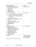


24
Service Supplement
TX100 S2
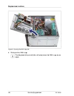
Replacement routines
Ê
If the server does not shut down properly, press and hold the On / Off button
for five seconds, until the server switches off.
Ê
Disconnect the AC power cord from the system.
Ê
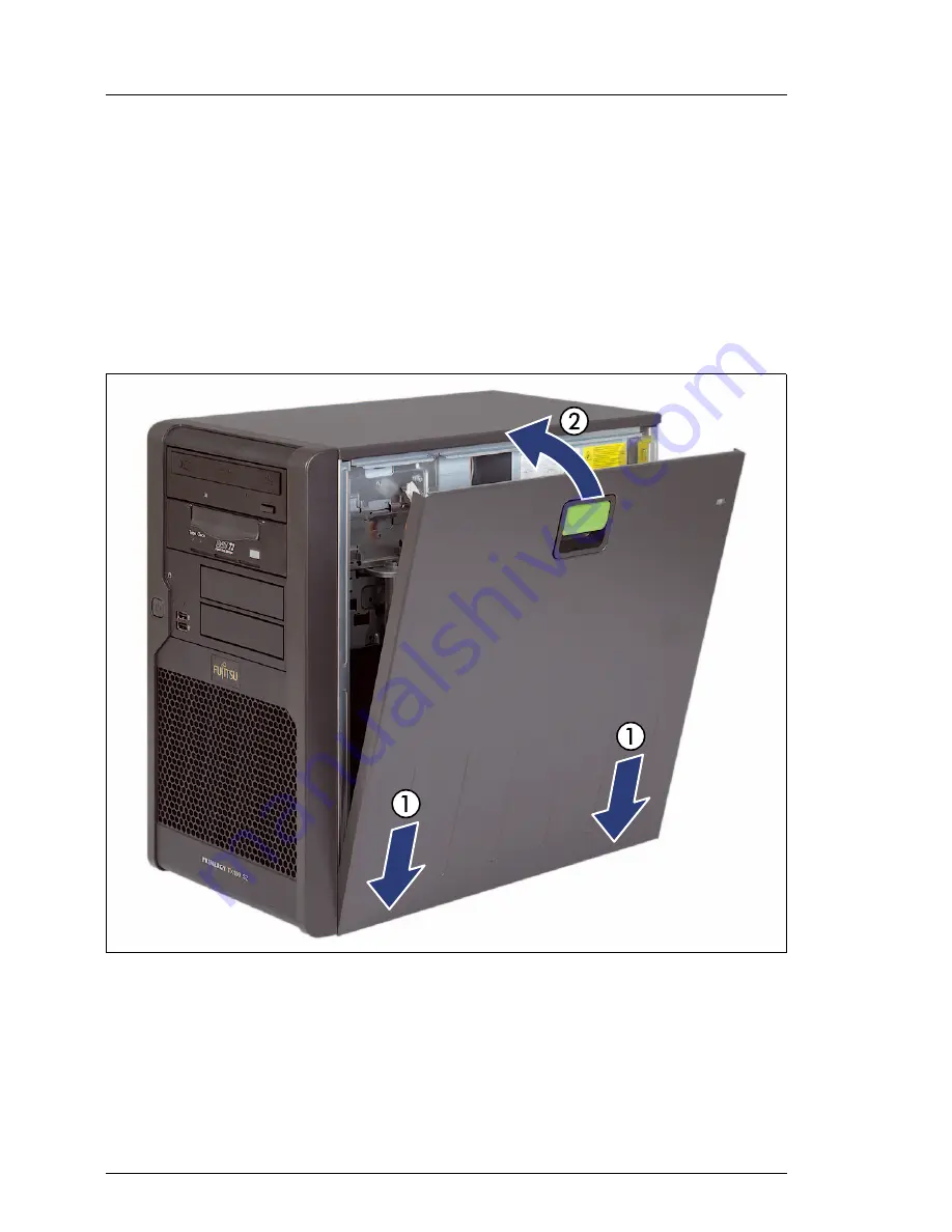
Pull the locking lever (1) and fold out the side cover (2).
Ê
Unlatch and remove the side cover (3).
4.1.1.2
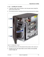
Closing the side cover
Figure 3: Closing the side cover
Ê
Latch the bottom edge of the side cover to the server chassis (1).
Ê
Close the side cover (2) until it locks in place.
Ê
Reconnect the AC power cord.
Summary of Contents for PRIMERGY TX100 S2
Page 1: ...Service Supplement English PRIMERGY TX100 S2 Server Service Supplement Edition July 2010 ...
Page 6: ......
Page 14: ......
Page 22: ......


