TX1320 M1
Operating Manual
53
Hardware installation
5.3
Connecting devices to the server
The connectors for external devices are on the front and rear of the server. The
additional connectors available on your server depend on the expansion cards
installed.
The standard connectors are indicated by symbols and color coding:
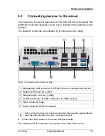
Figure 7: Connector panel on the rear side
I
Some of the devices that can be connected may require special drivers
(see the documentation for the connected device).
Ê
Connect the data cables to the server and peripherals.
Two additional USB connectors are located on the front of the server.
1 Management LAN connector, for iRMC S4 server management function
2 Shared LAN connector (LAN1)
3 Standard LAN connector (LAN2)
4 6 USB connectors: 4x USB 2.0 (black); 2x USB3.0 (blue)
5 Video connector (blue)
6 Serial connector COM1 (turquoise)
햶
햷
햵
햲
햴
햳
Summary of Contents for PRIMERGY TX1320 M1
Page 1: ...Operating Manual English FUJITSU Server PRIMERGY TX1320 M1 Operating Manual Edition July 2014 ...
Page 6: ...Operating Manual TX1320 M1 ...
Page 10: ...Operating Manual TX1320 M1 Contents ...
Page 14: ...14 Operating Manual TX1320 M1 Introduction ...
Page 30: ...30 Operating Manual TX1320 M1 Functional overview ...
Page 58: ...58 Operating Manual TX1320 M1 Hardware installation ...
Page 80: ...80 Operating Manual TX1320 M1 Property and data protection ...
Page 86: ...86 Operating Manual TX1320 M1 Troubleshooting and tips ...


