TX140 S1
Upgrade and Maintenance Manual
111
Basic software procedures
5.2.8
Enabling replaced components in the system BIOS
When a processor, an expansion card, or a memory module fails, the defective
component will be set to
Disabled
or
Failed
in the system BIOS. The server will
then reboot with only the intact hardware components remaining in the system
configuration. After replacing the defective component, it needs to be re-
enabled in the system board BIOS.
Ê
Enter the BIOS.
Ê
Select the
Advanced
menu.
Ê
Select the status menu of the desired component:
– Processors:
CPU Status
I
This option is only available for multi-processor systems.
– Memory:
Memory Status
– Expansion cards:
PCI Status
Ê
Reset replaced components to
Enable
.
Ê
Save your changes and exit the BIOS.
I
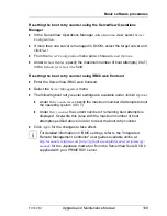
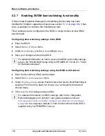
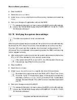
For detailed information on how to access the BIOS and modify settings,
refer to the "D3049 BIOS Setup Utility for PRIMERGY TX140 S1 / TX120
S3 Reference Manual".
5.2.9
Verifying the memory mode
If a memory module fails, the server will reboot and the defective module will be
disabled. As a result, the current operation mode (e.g. Mirrored Channel mode)
may no longer be available due to a lack of identical memory module pairs. In
this case, the operation mode will automatically revert to Independent Channel
Mode.
I
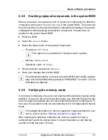
For detailed information on memory operation modes available for your
server, refer to section
"Memory sequence" on page 294
.
After replacing the defective module(s) the memory operation mode is
automatically reset to its original state. It is recommended to verify that the
operation mode has been correctly.
Summary of Contents for PRIMERGY TX140 S1
Page 6: ...Upgrade and Maintenance Manual TX140 S1 ...
Page 22: ...Upgrade and Maintenance Manual TX140 S1 Contents ...
Page 24: ...24 Upgrade and Maintenance Manual TX140 S1 ...
Page 40: ...40 Upgrade and Maintenance Manual TX140 S1 Before you start ...
Page 204: ...204 Upgrade and Maintenance Manual TX140 S1 Hard disk drives solid state drives ...
Page 292: ...292 Upgrade and Maintenance Manual TX140 S1 Expansion cards and backup units ...
Page 306: ...306 Upgrade and Maintenance Manual TX140 S1 Main memory ...
Page 370: ...370 Upgrade and Maintenance Manual TX140 S1 Accessible drives ...
Page 414: ...414 Upgrade and Maintenance Manual TX140 S1 Front panel and external connectors ...
Page 472: ...472 Upgrade and Maintenance Manual TX140 S1 System board and components ...
Page 568: ...568 Upgrade and Maintenance Manual TX140 S1 Cabling ...

