
326
Upgrade and Maintenance Manual
TX140
S1
Processors
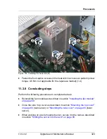
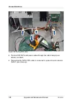
11.3.6 Concluding steps
Perform the following procedures to complete the task:
Ê
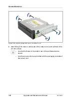
Reinstall the fan module as described in section
"Installing the fan module"
on page 209
.
Ê
Close the side / top cover as described in section
"Mounting the top cover"
on page 80
(rack server) or
"Mounting the side cover" on page 85
(tower
server).
Ê
When working on a rack-mounted server, secure it in the rack as described
in section
"Sliding the server into the rack" on page 89
.
If the server has been completely removed from the rack for maintenance
purposes, reinstall and secure it in the rack as described in section
"Mounting the server in the rack" on page 87
.
Ê
Reconnect the AC power cord to the power supply unit as described in
section
"Switching on the server" on page 91
.
Ê
Reconnect the AC power cord to the power supply unit and secure it with a
cable tie as described in section
"Connecting the server to the mains" on
page 90
.
Ê
If applicable, close the rack door as described in section
"Closing the rack
door" on page 92
.
Summary of Contents for PRIMERGY TX140 S1
Page 6: ...Upgrade and Maintenance Manual TX140 S1 ...
Page 22: ...Upgrade and Maintenance Manual TX140 S1 Contents ...
Page 24: ...24 Upgrade and Maintenance Manual TX140 S1 ...
Page 40: ...40 Upgrade and Maintenance Manual TX140 S1 Before you start ...
Page 204: ...204 Upgrade and Maintenance Manual TX140 S1 Hard disk drives solid state drives ...
Page 292: ...292 Upgrade and Maintenance Manual TX140 S1 Expansion cards and backup units ...
Page 306: ...306 Upgrade and Maintenance Manual TX140 S1 Main memory ...
Page 370: ...370 Upgrade and Maintenance Manual TX140 S1 Accessible drives ...
Page 414: ...414 Upgrade and Maintenance Manual TX140 S1 Front panel and external connectors ...
Page 472: ...472 Upgrade and Maintenance Manual TX140 S1 System board and components ...
Page 568: ...568 Upgrade and Maintenance Manual TX140 S1 Cabling ...