438
Upgrade and Maintenance Manual
TX140
S1
System board and components
Ê
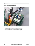
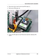
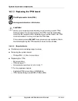
Shut down the server as described in section
"Shutting down the server" on
page 61
.
Ê
Remove the AC power cord from the cable tie and disconnect it from the
system as described in section
"Disconnecting power cords" on page 63
.
Ê
When working on a rack-mounted server, extend it out of the rack as
described in section
"Extending the server out of the rack" on page 65
.
If further required, remove the server from the rack as described in section
"Removing the server from the rack" on page 66
.
Ê
Open the side / top cover as described in section
"Removing the top cover"
on page 67
(rack server) or
"Removing the side cover" on page 71
(tower
server).
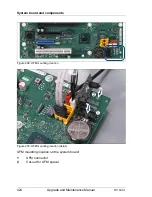
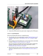
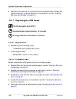
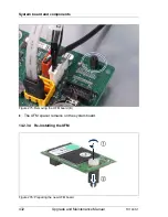
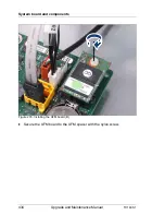
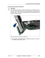
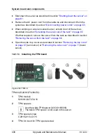
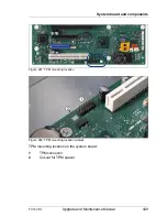
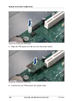
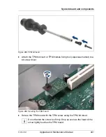
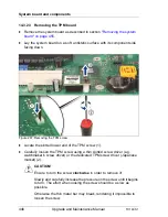
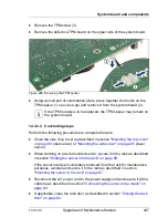
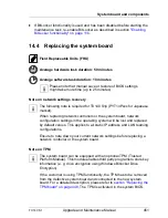
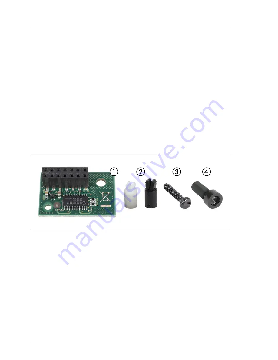
14.3.1.3 Installing the TPM board
Figure 280: TPM kit
TPM kit (S26361-F3299-E2):
1
TPM module
S26361-D2727-A10
2
TPM spacers
I
Use the white TPM spacer (A3C40106008).
The black TPM spacer is not used in this server.
3
TPM special screw
C26192-Y10-C176
4
TPM bit insert for TPM special screw
Summary of Contents for PRIMERGY TX140 S1
Page 6: ...Upgrade and Maintenance Manual TX140 S1 ...
Page 22: ...Upgrade and Maintenance Manual TX140 S1 Contents ...
Page 24: ...24 Upgrade and Maintenance Manual TX140 S1 ...
Page 40: ...40 Upgrade and Maintenance Manual TX140 S1 Before you start ...
Page 204: ...204 Upgrade and Maintenance Manual TX140 S1 Hard disk drives solid state drives ...
Page 292: ...292 Upgrade and Maintenance Manual TX140 S1 Expansion cards and backup units ...
Page 306: ...306 Upgrade and Maintenance Manual TX140 S1 Main memory ...
Page 370: ...370 Upgrade and Maintenance Manual TX140 S1 Accessible drives ...
Page 414: ...414 Upgrade and Maintenance Manual TX140 S1 Front panel and external connectors ...
Page 472: ...472 Upgrade and Maintenance Manual TX140 S1 System board and components ...
Page 568: ...568 Upgrade and Maintenance Manual TX140 S1 Cabling ...


