466
Upgrade and Maintenance Manual
TX140
S1
System board and components
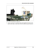
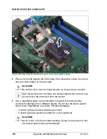
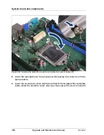
Figure 300: Removing the protective socket cover (new system board)
Ê
Place your thumb against the front edge of the protective socket cover and
rest your index finger on the rear grip.
V
CAUTION!
Be careful not to touch or bend the pins on the processor socket!
I
Save the socket cover for future use. Always replace the socket cover
if you remove the processor from the socket.
Ê
Use a magnifying glass (recommended) to inspect the socket spring
contacts for damages from different angles. Do not use the spare system
board if any irregularities are visible. Possible damages:
– Contact spring is bent backwards upon itself
– Contact spring tip position is shifted or out of alignment
V
CAUTION!
Never not try to fix bent contact springs. Doing so may result in loss
of electrical performance and reliability.
Summary of Contents for PRIMERGY TX140 S1
Page 6: ...Upgrade and Maintenance Manual TX140 S1 ...
Page 22: ...Upgrade and Maintenance Manual TX140 S1 Contents ...
Page 24: ...24 Upgrade and Maintenance Manual TX140 S1 ...
Page 40: ...40 Upgrade and Maintenance Manual TX140 S1 Before you start ...
Page 204: ...204 Upgrade and Maintenance Manual TX140 S1 Hard disk drives solid state drives ...
Page 292: ...292 Upgrade and Maintenance Manual TX140 S1 Expansion cards and backup units ...
Page 306: ...306 Upgrade and Maintenance Manual TX140 S1 Main memory ...
Page 370: ...370 Upgrade and Maintenance Manual TX140 S1 Accessible drives ...
Page 414: ...414 Upgrade and Maintenance Manual TX140 S1 Front panel and external connectors ...
Page 472: ...472 Upgrade and Maintenance Manual TX140 S1 System board and components ...
Page 568: ...568 Upgrade and Maintenance Manual TX140 S1 Cabling ...

