584
Upgrade and Maintenance Manual
TX140
S1
Appendix
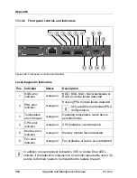
17.3.2.2 Front panel controls and indicators
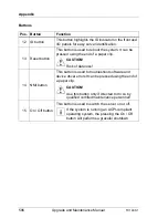
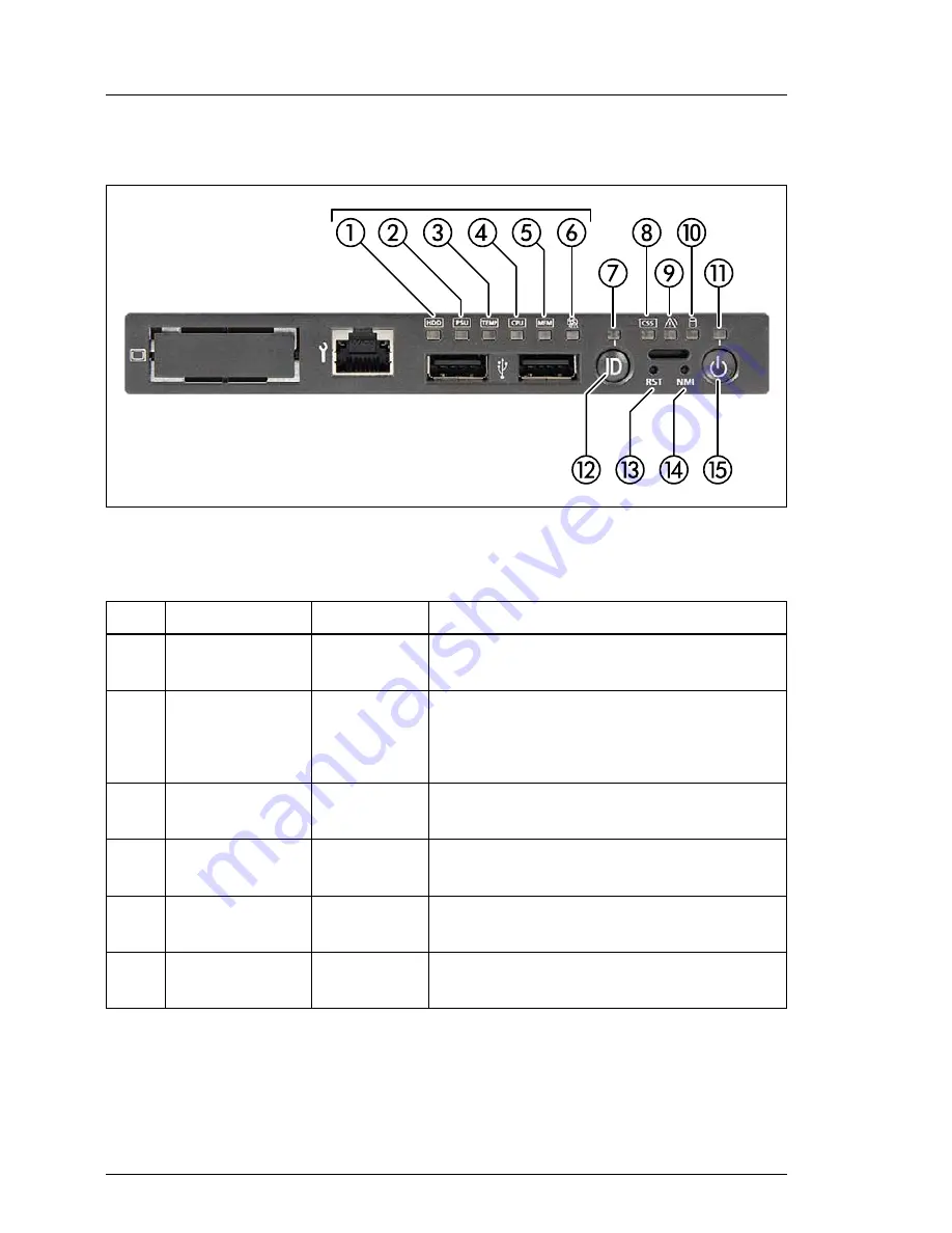
Figure 408: Front panel controls and indicators
Local diagnostic indicators
I
In addition to local dignostic indicators, CSS or Global Error LEDs
indicate, if the defective component is a customer replaceable unit or if a
service technician needs to be dispatched to replace the part.
Pos. Indicator
Status
Description
1
HDD error
indicator
orange on
HDD / SSD, SAS / SATA backplane or
RAID controller failure detected
2
PSU error
indicator
orange on
Hot-plug PSU module failure detected
I
Only available in redundant PSU
configurations.
3
Temperature
error indicator
orange on
Operating temperature levels above
permitted limits
4
CPU error
indicator
orange on
CPU prefailure event detected
5
Memory error
indicator
orange on
Memory module failure detected
6
Fan error
indicator
orange on
Fan prefailure or failure event detected
Summary of Contents for PRIMERGY TX140 S1
Page 6: ...Upgrade and Maintenance Manual TX140 S1 ...
Page 22: ...Upgrade and Maintenance Manual TX140 S1 Contents ...
Page 24: ...24 Upgrade and Maintenance Manual TX140 S1 ...
Page 40: ...40 Upgrade and Maintenance Manual TX140 S1 Before you start ...
Page 204: ...204 Upgrade and Maintenance Manual TX140 S1 Hard disk drives solid state drives ...
Page 292: ...292 Upgrade and Maintenance Manual TX140 S1 Expansion cards and backup units ...
Page 306: ...306 Upgrade and Maintenance Manual TX140 S1 Main memory ...
Page 370: ...370 Upgrade and Maintenance Manual TX140 S1 Accessible drives ...
Page 414: ...414 Upgrade and Maintenance Manual TX140 S1 Front panel and external connectors ...
Page 472: ...472 Upgrade and Maintenance Manual TX140 S1 System board and components ...
Page 568: ...568 Upgrade and Maintenance Manual TX140 S1 Cabling ...

