background image

TX140 S1

Operating Manual

39

Important information

Do not contaminate the CD/DVD/BD surface with fingerprints, oil, 
dust, etc. If dirty, clean with a soft, dry cloth, wiping from the center to 
the edge. Do not use benzene, thinners, water, record sprays, 
antistatic agents, or silicone-impregnated cloth.

Be careful not to damage the CD/DVD/BD surface.

Keep the CDs/DVDs/BDs away from heat sources.

Do not bend or place heavy objects on CDs/DVDs/BDs.

Do not write with ballpoint pen or pencil on the label (printed) side.

Do not attach stickers or similar to the label side. Doing so may cause 
rotational eccentricity and abnormal vibrations.

When a CD/DVD/BD is moved from a cold place to a warm place, 
moisture condensation on the CD/DVD/BD surface can cause data 
read errors. In this  case, wipe the CD/DVD/BD with a soft, dry cloth 
then let it air dry. Do not dry the CD/DVD/BD using devices such as a 
hair dryer.

To avoid dust, damage, and deformation, keep the CD/DVD/BD in its 
case whenever it is not in use.

Do not store CDs/DVDs/BDs at high temperatures. Areas exposed to 
prolonged direct sunlight or near heating appliances are to be 
avoided.

I

You can prevent damage from the optical drive and the CDs/DVDs/BDs, 
as well as premature wear of the disks, by observing the following 
suggestions:

– Only insert disks in the drive when needed and remove them after 

use.

– Store the disks in suitable sleeves.
– Protect the disks from exposure to heat and direct sunlight.
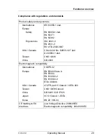
Laser information

The optical drive complies with IEC 60825-1 laser class 1.

V

CAUTION!

The optical drive contains a light-emitting diode (LED), which under 
certain circumstances produces a laser beam stronger than laser 
class 1. Looking directly at this beam is dangerous.

Never remove parts of the optical drive casing!

Summary of Contents for PRIMERGY TX140 S1

Page 1: ...Operating Manual English PRIMERGY TX140 S1 Server Operating Manual Edition June 2011 ...

Page 2: ... Copyright and Trademarks Copyright 2011 Fujitsu Technology Solutions GmbH All rights reserved Delivery subject to availability right of technical modifications reserved All hardware and software names used are trademarks of their respective manufacturers The contents of this manual may be revised without prior notice Fujitsu assumes no liability for damages to third party copyrights or other righ...

Page 3: ...n the mouse and keyboard are limited life components Use of these components beyond their operating life may result in electrolyte leakage or depletion potentially causing emission of foul odor or smoke As a guideline in a normal office environment 25 C operating life is not expected to be reached within the maintenance support period 5 years However operating life may be reached more quickly if f...

Page 4: ...omentary voltage drop in the power supply caused by lightning To prevent a momentary voltage drop use of an AC uninterruptible power supply is recommended This notice follows the guidelines of Voltage Dip Immunity of Personal Computer issued by JEITA the Japan Electronics and Information Technology Industries Association Technology controlled by the Foreign Exchange and Foreign Trade Control Law o...

Page 5: ...epending on the type of hard disk drive used Please refer to the following internet address for further information on the usage and operation conditions of each available type of hard disk drive http primeserver fujitsu com primergy harddisk Only for the Japanese market I Although described in this manual some sections do not apply to the Japanese market These options and routines include USB Fla...

Page 6: ...Operating Manual TX140 S1 ...

Page 7: ... 31 4 Important information 33 4 1 Safety instructions 33 4 2 ENERGY STAR 41 4 3 CE conformity 41 4 4 FCC Class A Compliance Statement 42 4 5 Transporting the server 43 4 6 Notes on installing the server in the rack 44 4 7 Environmental protection 45 5 Hardware installation 47 5 1 Unpacking the server 48 5 2 Setting up the floorstand model 49 5 3 Installing removing the rack model 50 5 3 1 Rack sy...

Page 8: ...rol panel 65 6 2 1 4 Indicators on the drives 66 6 2 2 Rear of server 68 6 2 2 1 Indicators on the connector panel 68 6 3 Switching the server on and off 71 6 4 Configuring the server 74 6 4 1 Configuring the onboard SATA controller 74 6 4 2 Configuring the SAS SATA RAID controller 75 6 4 3 Configuring the server and installing the operating system with the ServerView Installation Manager 76 6 4 4...

Page 9: ... mouse pointer displayed on screen 83 8 7 Incorrect date and time 84 8 8 Drives reported as dead when starting system 84 8 9 Added drive reported as defective 84 8 10 Error message on screen 85 8 11 Expansion cards or onboard devices not recognized 85 8 12 Temperature warning 85 8 13 No effect of keyboard or mouse 85 8 14 Optical drive cannot read data 86 ...

Page 10: ...Operating Manual TX140 S1 Contents ...

Page 11: ...configuration and Restart ASR R Security functions in the BIOS Setup and on the system board protect the data on the server against manipulation Additional security is provided by the lockable drive cover on the floorstand model and the lockable rack door on the rack model The rack model occupies 5 height units in the rack 1 1 Concept and target groups for this manual This operating manual describ...

Page 12: ... only included with the ServerView Suite as a printed copy Safety Notes and Regulations manual 安全上のご注意 for the Japanese market Warranty manual 保証書 for the Japanese market ServerView Suite Local Service Concept LSC manual Returning used devices manual and Service Desk leaflet サポート サービス for the Japanese market PRIMERGY TX140 S1 Upgrade and Maintenance Manual System Board D3049 for PRIMERGY TX140 S1 ...

Page 13: ...he online documentation available on the Internet can be found using the URL for EMEA market http manuals ts fujitsu com The PRIMERGY server documentation can be accessed using the Industry standard servers navigation option For the Japanese market Please see following URL about the latest manual of the product http primeserver fujitsu com primergy manual Other remarks that have not been described...

Page 14: ...nu items Quotation marks indicate names of chapters and terms that are being emphasized Ê describes activities that must be performed in the order shown V CAUTION pay particular attention to texts marked with this symbol Failure to observe this warning may endanger your life destroy the system or lead to the loss of data I indicates additional information notes and tips ...

Page 15: ...component yourself in the case of certain error scenarios In the CSS concept you can replace the following components yourself in the event of an error Hot plug hard disk drives Hot plug power supply units Memory modules System fans Expansion cards For information on replacing these components see the PRIMERGY TX140 S1 Upgrade and Maintenance Manual CSS indicators on the control panel and on the b...

Page 16: ...nical manual for the system board D3049 for the hardware and in the BIOS Setup manual for the firmware Trusted Platform Module TPM A Trusted Platform Module TPM for safer storage of keys can be implemented as an option This module enables programs from third party manufacturers to store key information e g drive encryption using Windows Bitlocker Drive Encryption The TPM is activated via the BIOS ...

Page 17: ...SD drives Up to eight 2 5 inch HDD SSD modules can be used in the drive cage Each module can accommodate SAS SATA hard disk drive or an SATA SSD drive with a 2 5 inch format The HDD SSD modules are connected to the SAS SATA backplane wirelessly This allows modules to be plugged in or pulled out easily I Up to eight SAS SATA hard disk drives are controlled by the SAS SATA RAID controller already in...

Page 18: ...RAID levels 0 1 10 1E 5 50 6 and 60 are supported for internal hard disk drive configurations As an option a battery backup unit BBU can save the memory content even if the power fails Cache memory size of 512 Mbyte is available I For more information on configuring the controller see section Configuring the SAS SATA RAID controller on page 75 Further information on SAS SATA RAID controllers is pr...

Page 19: ...ess to the 5 25 inch drives Power supply The server has a permanently installed power supply unit that adjusts automatically to any mains voltage in the range 100 V 240 V High level of availability and data security When memory data is accessed 1 bit errors are identified in the main memory and automatically corrected with the error correcting code ECC method ASR R Automatic Server Reconfiguration...

Page 20: ...nt for the managed server depending on its system status Power Consumption Management Connecting virtual drives as remote storage Text based and graphic console bypass Advanced Video Redirection Remote Storage Command Line Interface CLI Simple interactive or script based iRMC S3 configuration Customer Self Service CSS iRMC S3 s own user management Multi computer global iRMC S3 user administration ...

Page 21: ...ns Round the clock monitoring regardless of server status High performance graphical console bypass AVR protected by HTTPS SSL 128 bit Remote storage via USB Remote power on Intrusion detection in the floorstand model Temperature monitoring of the CPU and the surrounding area Detailed status and error reports for processors and main memory Watchdog timer for Automatic Server Reconfiguration and Re...

Page 22: ...d immediate recognition In order to prevent the components from being damaged by incorrect handling when they are being installed and removed the areas of all components that can be touched without damaging them are also marked green PRIMERGY diagnostic LEDs fitted on the system board show which component memory module processor fan or expansion card is not functioning properly The Flash EPROM pro...

Page 23: ... a reduction in the total cost of ownership and an excellent return on investment for the remote management solution The administrator can access all system information and information from the sensors such as fan speeds or voltages via the iRMC S3 s Web interface see section iRMC S3 with integrated management LAN connector on page 20 You can also start the text based or graphic console bypass Adv...

Page 24: ...el Xeon Pentium Core i3 processor Memory slots 4 Memory slot type DIMM DDR3 Memory capacity min max 2 GB 32 GB Memory protection ECC Memory notes 1333 MHz memory modules with 2 4 or 8GB USB connectors 10 x USB 2 0 2x front 6x rear 2x internal USB1 AUX and USB1 DAT connot be used in parallel Graphics 15 pin 1 x VGA Serial 1 9 pin 1 x serial RS 232 C usable for iRMC or system or shared LAN Ethernet ...

Page 25: ...h MegaRAID functionality SAS MegaRAID for SAS1 0 and SAS2 0 RAID levels 0 1 10 1E 5 50 6 and 60 are supported for internal hard disk drive configurations SATA Controller A 6 port SATA controller is integrated on the system board up to four SATA hard disk drives can be connected to the controller The LSI Embedded MegaRAID software SATA Software RAID supports RAID levels 0 1 and 10 Remote Management...

Page 26: ...possible options described in relevant system configurator Operating buttons On off switch NMI button Reset button ID button Status LEDs System status orange yellow Identification blue Hard disks access green Power orange green CSS yellow HDD orange PSU orange TEMP orange CPU orange MEM orange FAN orange Status LED at system rear side System status orange yellow Identification blue LAN connection ...

Page 27: ...D x H 205 x 584 x 444 mm Rack W x D x H 482 x 570 x 220 mm Mounting Depth Rack 617 mm Weight Approx 21 28 kg Weight notes Weight may vary depending on actual configuration Rack mounting kit Rack mounting kit as option Environment class 3K2 Environment class 2K2 EN 60721 IEC 721 Part 3 3 EN 60721 IEC 721 Part 3 2 Temperature Operation 3K2 10 C 35 C Transport 2K2 25 C 60 C Humidity 10 85 non condens...

Page 28: ...296 4 2 B standby 4 2 B operation 4 9 B standby 5 1 B operation Sound pressure level at adjacent workstation LpAm ISO 9296 25 dB A standby 25 dB A operation 31 dB A standby 33 dB A operation Power supply configuration 1x standard power supply Max output 300 W Rated voltage range 100 240 V Rated frequency range 47 Hz 63 Hz Rated current max 6 0 A 3 0 A 100 V 240 V ...

Page 29: ...07 USA Canada CSA C22 2 No 60950 1 07 2ed UL 60950 1 2ed Taiwan CNS 14336 China GB 4943 Electromagnetic compatibility International CISPR 22 Europe EN 55022 Class A EN 55024 EN 61000 3 2 EN 61000 3 3 ETSI 300386 USA Canada 47CFR part 15 Class A ICES 003 Taiwan CNS 13438 Class A China GB 9245 GB 17625 Japan VCCI Class A JEITA Korea KN 22 KN 24 CE marking to EU directives Low Voltage Directive 2006 ...

Page 30: ...30 Operating Manual TX140 S1 Functional overview ...

Page 31: ... additionally may be delivered loose with the server Install these in the server as described in the supplied documentation Ê Set up the floorstand model see section Setting up the floorstand model on page 49 or install the rack model in the rack see section Installing removing the rack model on page 50 Ê Wire the server Follow the instructions in sections Connecting devices to the server on page ...

Page 32: ... system with the ServerView Installation Manager on page 76 Local configuration and installation with or without the ServerView Installation Manager see section Configuring the server and installing the operating system with the ServerView Installation Manager on page 76 or section Configuring the server and installing the operating system without the ServerView Installation Manager on page 77 I Y...

Page 33: ...formed by technical specialists A technical specialist is a person who is trained to install the server including hardware and software Repairs to the device that do not relate to CSS failures shall be performed by service personnel Please note that unauthorized interference with the system will void the warranty and exempt the manufacturer from all liability Any failure to observe the guidelines ...

Page 34: ...ing that protects it from impacts and jolts Installation and operation V CAUTION This unit should not be operated in ambient temperatures above 35 C If the unit is integrated into an installation that draws power from an industrial power supply network with an IEC309 connector the power supply s fuse protection must comply with the requirements for non industrial power supply networks for type A c...

Page 35: ...elded Ethernet cabling has to comply with EN 50173 and EN 50174 1 2 standards or ISO IEC 11801 standard respectively The minimum requirement is a Category 5 shielded cable for 10 100 Ethernet or a Category 5e cable for Gigabit Ethernet Route the cables in such a way that they do not create a potential hazard make sure no one can trip over them and that they cannot be damaged When connecting the se...

Page 36: ...warranty is void if the server is damaged during installation or replacement of system expansions Only set screen resolutions and refresh rates that are specified in the operating manual for the monitor Otherwise you may damage your monitor If you are in any doubt contact your sales outlet or customer service center Before installing removing internal options to from the server turn off the server...

Page 37: ...placed with identical batteries or with a type recommended by the manufacturer see the PRIMERGY TX140 S1 Upgrade and Maintenance manual Do not throw batteries into the trash can Batteries must be disposed of in accordance with local regulations concerning special waste Replace the lithium battery on the system board in accordance with the instructions in the PRIMERGY TX140 S1 Upgrade and Maintenan...

Page 38: ...uipment damage and can fly out of the device danger of injury particularly to uncovered body parts such as the face or neck High humidity and airborne dust levels are to be avoided Electric shocks and or server failures may be caused by liquids such as water or metallic items such as paper clips entering a drive Shocks and vibrations are also to be avoided Do not insert any objects other than the ...

Page 39: ...e the CD DVD BD with a soft dry cloth then let it air dry Do not dry the CD DVD BD using devices such as a hair dryer To avoid dust damage and deformation keep the CD DVD BD in its case whenever it is not in use Do not store CDs DVDs BDs at high temperatures Areas exposed to prolonged direct sunlight or near heating appliances are to be avoided I You can prevent damage from the optical drive and t...

Page 40: ...ays discharge static build up e g by touching a grounded object before working with such components Any devices or tools that are used must be free of electrostatic charge Wear a suitable grounding cable that connects you to the external chassis of the system unit Always hold components with ESDs at the edges or at the points marked green touch points Do not touch any connectors or conduction path...

Page 41: ... Note that energy consumption can be affected by software that is installed or any changes that are made to the hardware configuration or BIOS or energy options subsequently In such cases the properties guaranteed by ENERGY STAR can no longer be assured The ServerView Operations Manager user guide contains instructions for reading out measurement values including those relating to current energy c...

Page 42: ...l interference to radio or television reception which can be determined by turning the equipment off and on the user is encouraged to try to correct the interference by one or more of the following measures Reorient or relocate the receiving antenna Increase the separation between equipment and the receiver Connect the equipment into an outlet on a circuit different from that to which the receiver...

Page 43: ...port the server in its original packaging or in packaging that protects it from impacts and jolts Do not unpack the server until it is at its installation location If you need to lift or transport the server ask other people to help you Never lift or carry the device by the handles on the front panel ...

Page 44: ...e technical manual is supplied with the corresponding rack When installing the rack make sure that the anti tilt mechanism is correctly fitted For safety reasons no more than one unit may be removed from the rack at any one time during installation and maintenance work If several units are simultaneously removed from the rack there is a risk that the rack could tip over The rack must be connected ...

Page 45: ...switched on should be switched off until they are needed as well as during long breaks and after completion of work Packaging information This packaging information doesn t apply to the Japanese market Do not throw away the packaging You may need it later for transporting the system If possible the equipment should only be transported in its original packaging Information on handling consumables P...

Page 46: ...d devices manual via your local Fujitsu branch or from our recycling center in Paderborn Fujitsu Technology Solutions Recycling Center D 33106 Paderborn Tel 49 5251 525 1410 Fax 49 5251 525 32 1410 The device must not be disposed of with domestic waste This device is labeled in compliance with European directive 2002 96 EC on waste electrical and electronic equipment WEEE This directive sets the f...

Page 47: ... and heat Make sure that the server is acclimatized for the time indicated in this table before putting it into operation In the table Acclimatization time the temperature difference refers to the difference between the operating environment temperature and the temperature to which the server was exposed previously outside transport or storage temperature Temperature difference C Minimum acclimati...

Page 48: ...rt the server to the place where you want to set it up Ê Unpack all individual parts Keep the original packaging in case you want to transport the server again applies only to EMEA market Ê Check the delivery for any damage during transport Ê Check whether the items delivered match the details on the delivery note The product name and serial number of the product can be found on the ID card see se...

Page 49: ...from direct sunlight The required minimum distances for operation and maintenance areas must be adhered to The server must be accessible at the rear for connection to other devices e g memory subsystem The mains plug must be accessible easily and safely There must be a clearance of at least 200 mm in front of and behind the server to ensure adequate ventilation of the subsystem Ê Wire the server F...

Page 50: ...The rack systems from Fujitsu PRIMECENTER Rack DataCenter Rack and 19 inch standard rack for the Japanese market support the installation of PRIMERGY servers Installation in most current rack systems from other manufacturers 3rd party racks is also supported To accommodate the ventilation concept and ensure proper ventilation any unused areas in the rack must be sealed using dummy covers The power...

Page 51: ...ructure guide 3rd party racks Certain general conditions must be met Installation dimensions see the dimensions shown in figure 2 on page 52 1 Front of rack 2 Rear of rack A Rack depth comparison PRIMECENTER Rack 940 1000 1100 mm B Rack width comparison PRIMECENTER rack 700 mm C Clearance for 19 installation level C1 Front 19 installation level C2 Rear 19 installation level D Cable routing area ca...

Page 52: ...52 Operating Manual TX140 S1 Hardware installation Figure 2 Mechanical requirements 735 770 mm 100 mm 1 6mm ...

Page 53: ...An unobstructed air intake in the rack front and air discharge in the rear cover of the rack are essential for ventilation of the installed server In general the ventilation concept ensures that the necessary cooling is achieved by the horizontal self ventilation of the installed devices air flow from the front to the rear Power supply For installation in 3rd party racks you must ensure that the a...

Page 54: ...nual The standard connectors are indicated by symbols and color coding Figure 3 Connector panel on the rear side I Some of the devices that can be connected may require special drivers see the documentation for the connected device Ê Connect the data cables to the server and peripherals Two additional USB connectors are located on the front of the server see figure 8 on page 62 1 Service LAN conne...

Page 55: ...label on the monitor or in the operating manual for the monitor 5 5 Connecting the server to the mains The server is equipped with an integrated power supply unit V CAUTION The server is automatically set to a mains voltage in the range 100 V 240 V You may only operate the server if its rated voltage range corresponds to the local mains voltage Ê Connect the power cord to the server power supply u...

Page 56: ...rom the server accidentally The cable tie is included in the accessories pack that is delivered together with the server Figure 4 Using cable ties Ê Thread the cable tie through the eye 1 Ê Pull the cable tie tight to secure the power cable The insulated connector cannot now be disconnected from the server accidentally You can loosen the cable tie by opening the small locking lever 2 0 ...

Page 57: ...ting cables Ê Turn off all power and equipment switches Ê Disconnect all power plugs from the properly grounded power outlets Ê Connect all cables to the server and peripherals Ê Plug all data communication cables into the utility sockets Ê Plug all power cords into the properly grounded power outlets Disconnecting cables Ê Turn off all power and equipment switches Ê Disconnect all power plugs fro...

Page 58: ...58 Operating Manual TX140 S1 Hardware installation ...

Page 59: ...ge 33 6 1 Access to the drives floorstand model 6 1 1 Enabling access to the accessible drives Figure 5 Removing the drive cover and snapping it into the HDD cover Ê Unlock the server 1 Ê Remove the drive cover 2 Ê Attach the drive cover to the recesses on the HDD cover 3 Ê Push down the HDD cover in the direction of the arrow 4 0 1 2 3 ...

Page 60: ... If the system is programmed to eject the media automatically the accessible drives must not be obstructed The drive cover is replaced and the server locked in the reverse order Figure 6 Removing the drive cover from the HDD cover Ê Carefully pull out on the green release lever 1 and lift off the drive cover 2 0 1 ...

Page 61: ...al 61 Starting up and operation 6 1 2 Enabling access to the HDD modules Figure 7 Removing the HDD cover Ê Unlock the server 1 Ê Remove the HDD cover 2 The HDD cover is replaced and the server locked in the reverse order 0 1 ...

Page 62: ...ade and Maintenance manual 1 HDD error indicator 10 HDD SSD activity indicator 2 PSU error indicator 11 Power on indicator 3 Temperature error indicator 12 On Off button 4 CPU error indicator 13 NMIbutton 5 Memory error indicator 14 REST button 6 Fan error indicator 15 ID button 7 ID indicator 16 USB connector 8 CSS indicator 17 USB connector 9 Global Error indicator 18 Front management LAN connec...

Page 63: ...e 9 ID card You can pull out the ID card as far as it will go and push it back again The ID card contains various system information such as the product name serial number order number MAC addresses and DNS name in the Japanese market only the product name and the serial number ...

Page 64: ... switch off the system V CAUTION Risk of loss of data I The On Off button does not disconnect the server from the mains voltage To disconnect from the mains completely remove the power plug s NMI NMI button V CAUTION Do not press Risk of loss of data The NMI button may only be used by service RST Reset button Pressing the reset button reboots the system V CAUTION Risk of loss of data ID ID button ...

Page 65: ...icator orange Lights up orange if a prefailure event has been detected that requires precautionary service intervention Flashes orange if an error was detected that requires service intervention Does not light up if there is no critical event If the event is still acute after a power failure the indicator is activated after the restart The indicator also lights up in standby mode You can find more...

Page 66: ... with the CSS concept Does not light up when the system is OK If the event is still acute after a power failure the indicator is activated after the restart The indicator also lights up in standby mode For more information on the CSS concept see the PRIMERGY TX140 S1 Upgrade and Maintenance manual ID ID indicator blue Lights up blue when the system has been selected by pressing the ID button To de...

Page 67: ...HDD error On HDD Faulty drive defective needs replacing drive failed drive deactivated by software or the HDDmodule is not correctly inserted Slow flashing HDD Rebuild the data is being restored after changing a drive Fast flashing HDD Identify SATA server variant Does not light no HDD error On HDD Faulty or Rebuild Stopped drive defective and must be replaced a rebuild process was stopped or the ...

Page 68: ... if a prefailure event has been detected that requires precautionary service intervention Flashes orange if an error was detected that requires service intervention Does not light up if there is no critical event If the event is still acute after a power failure the indicator is activated after the restart The indicator also lights up in standby mode You can find more details on the indicated erro...

Page 69: ...If the event is still acute after a power failure the indicator is activated after the restart The indicator also lights up in standby mode For more information on the CSS concept see the PRIMERGY TX140 S1 Upgrade and Maintenance manual ID ID indicator blue Lights up blue when the system has been selected by pressing the ID button To deactivate press the button again The ID indicator can also be a...

Page 70: ...er information in the D3049 BIOS Setup Utility for PRIMERGY TX140 S1 TX120 S3 manual 1 LAN link transfer Steady green signal when a LAN connection exists Remains dark when no LAN connection exists Flashes green when LAN transfer takes place 2 LAN speed Steady yellow signal in the event of a LAN transfer rate of 1 Gbit s Steady green signal in the event of a LAN transfer rate of 100 Mbit s Remains ...

Page 71: ... environment the server may operate improperly damage data etc Furthermore Fujitsu cannot be held responsible for any related damage malfunction or loss of data etc Be sure to wait for 10 seconds or more after shutdown before turning the server on After connecting power cable press a power supply button after it passes for more than 10 seconds Switching the server on The power on indicator item 11...

Page 72: ...tem does not switch the server off automatically press the On Off button for at least four seconds and or send a corresponding control signal Other On Off options Besides the On Off button the server can be switched ON and OFF in the following ways Timer controlled switch on off Using the ServerView Operations Manager or iRMC S3 you can configure that the server is switched on off controlled by ti...

Page 73: ...r switch can be specified as Do Nothing Ask me what to do only for Windows Server 2003 Stand by Hibernate and Shutdown depending on the OS settings The default is Shutdown On this server functions corresponding to Stand by and Hibernate are supported as BIOS and hardware functions However some drivers and software installed in theserver do not support these functions For this reason functions corr...

Page 74: ...ystem board You can configure the onboard SATA controller either before or during installation with the ServerView Installation Manager Using the ServerView Installation Manager is recommended I The controller has its own configuration utility For further information refer to the Embedded MegaRAID Software User s Guide on the ServerView Suite DVD 2 under Industry Standard Servers Expansion Cards S...

Page 75: ...on the ServerView Suite DVD 2 under Industry Standard Servers Expansion Cards Storage Adapters LSI RAID SCSI Controllers A separate utility is available to the controller for MegaRAID configuration For further information refer to the SAS Software User s Guide on the ServerView Suite DVD 2 under Industry Standard Servers Expansion Cards Storage Adapters LSI Configuration Software Further informati...

Page 76: ...on of all leading server operating systems Wizard assisted creation of configuration files for unattended installation of several PRIMERGY servers with identical hardware configurations Installation of drivers and additional software I The software that can be installed depends on your server s hardware configuration This configuration is detected automatically I Descriptions of operating systems ...

Page 77: ...ATA RAID controller with Integrated Mirroring Enhanced Configure the controller as described in section Configuring the SAS SATA RAID controller on page 75 Configure SAS SATA RAID controller with MegaRAID functionality Configure the controller as described in section Configuring the SAS SATA RAID controller on page 75 Installing the operating system Ê Insert the CD DVD for the operating system you...

Page 78: ...gents that contain abrasives or may corrode plastic Ensure that no liquid enters the system Ensure that the ventilation areas of the server and the monitor are clear Do not use any cleaning sprays including flammable types It may cause a device failure or a fire Clean the keyboard and the mouse with a disinfecting cloth Wipe the server and monitor casing with a dry cloth If particularly dirty use ...

Page 79: ...to a fixed object with a steel cable running through a clip on the back The rack model is protected against unauthorized access by a lockable rack door To protect the system and data internally against unauthorized access you can activate the security functions of the BIOSSetup 7 1 BIOS Setup security functions The Security menu in BIOS Setup offers various options for protecting your data from un...

Page 80: ...80 Operating Manual TX140 S1 Property and data protection ...

Page 81: ...ist of the steps performed and the circumstances that led to the fault Also make a list of any error messages that were displayed Ê Switch off the server Ê Contact our customer service team 8 1 Power on indicator remains unlit The power on indicator remains dark after you switch on your device Power cable incorrectly connected Ê Make sure that the power cable s is are correctly connected to the se...

Page 82: ...riate password Brightness control is set to dark Ê Set the brightness control on the monitor to light For detailed information refer to the operating manual supplied with your monitor Power cable or monitor cable not connected Ê Switch off the monitor and the server Ê Check whether the power cable is properly connected to the monitor and to the grounded power outlet Ê Check whether the monitor cab...

Page 83: ...een display or display drifts The wrong horizontal frequency or resolution has been selected for the monitor or for the application program Ê Find out which horizontal frequency your monitor screen supports You will find the horizontal frequency also known as line frequency or horizontal deflection frequency in the documentation for your monitor Ê Refer to the documentation for your operating syst...

Page 84: ...tact our customer service team 8 8 Drives reported as dead when starting system This error message can occur when the onboard SAS controller has RAID functionality or the server is equipped with a PCI RAID controller RAID controller configuration incorrect Ê Check and correct the settings for the drives using the RAID controller utility Further information is provided in the manual for the RAID co...

Page 85: ... as by a popup message The above log is output or the above notification is issued by ServerView when the ambient temperature is within 30 to 35 C which is near the upper limit of the temperature boundaries 10 to 35 C This is to notify the administrator before the ambient temperature actually exceeds the range of the temperature boundaries Ê Although continued use within the temperature boundaries...

Page 86: ...he CD DVD BD is inserted properly If it is not inserted correctly insert the disk so that the label is facing up Ê Check to see whether the CD DVD BD is not dirty If it is dirty wipe it with a soft dry cloth Ê Check to see whether the CD DVD BD is not scratched or bent If scratched or damaged replace the CD DVD BD ...

Reviews: