30
Service Supplement
TX150
S5
Replacing the intrusion switches
Replacement routines
Ê
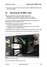
Take out the holder carefully.
Ê
Remove the green cable clamp from the connector of the I
2
C cable.
Ê
Remove the I
2
C cable from the connector on the IDTEMP combo.
Ê
Remove the IDTEMP combo from the holder.
Ê
Plug the new IDTEMP combo in the holder.
Ê
Plug the I
2
C cable on the connector on the IDTEMP combo.
Ê
Plug the green cable clamp on the connector of the I
2
C cable.
Ê
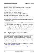
Insert the holder in a slight angle. Make sure that the cables are routed as
shown in
Ê
Push the holder in direction of the front side until the holder engage in the
bottom of the chassis.
Ê
Close the server and connect all power plugs (for a detailed description see
the Options Guide).
I
After installing the new IDTEMP combo, it is necessary to program the
ChassisID prom with the help of the "ChassisIDProm Tool" to enable
ServerView and ServerStart to identify the system. You will find the tool
on the ServerSupport CD and/or it can be downloaded from the Fujitsu
Siemens Computers Service and Support page (URL:
http://extranet.fujitsu-siemens.com/service/information/intelservers/tools
).
4.9
Replacing the intrusion switches
In the floorstand model two intrusion detection switches monitor the removing
of the left side cover and the hard disk cover. In the rack model only one
intrusion switch is active, this one monitors the removing of the top cover.
One switch is situated at the left (floorstand model) or the top (rack model) side
of the hard disk cage, the other switch at the front cover beneath the hard disk
cage. The two intrusion detection switches are serially connected on one cable
and have to be replaced in pairs.
Ê
Open the server and remove the front cover / rack front cover as described
in the
section “Preparation” on page 17
.
Ê
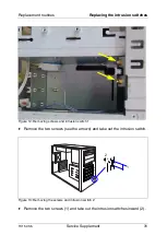
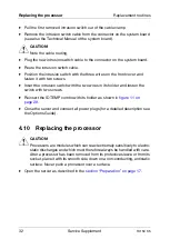
Remove the IDTEMP combo with its holder as shown in


