32
Service Supplement
TX150
S5
Replacing the processor
Replacement routines
Ê
Pull the first removed intrusion switch out of the cable clamp.
Ê
Remove the intrusion switch cable from the connector on the system board
(see also the Technical Manual of the system board).
V
CAUTION!
Note the cable routing.
Ê
Plug the new intrusion switch cable to the connector on the system board.
Ê
Route the intrusion switch cable.
Ê
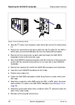
Position the intrusion switch with the three wires on the front cover and
fasten it with two screws.
Ê
Insert the intrusion switch with the two wires in its holder and fasten the
switch with two screws.
Ê
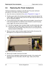
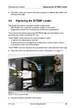
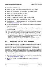
Reinsert the IDTEMP combo with its holder as shown in
Ê
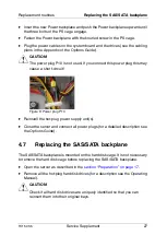
Close the server and connect all power plugs (for a detailed description see
the Options Guide).
4.10
Replacing the processor
V
CAUTION!
Processors are modules which can react extremely sensitively to electro-
static discharges and which must therefore always be handled with care.
After a processor has been removed from its protective sleeve or from its
socket, place it with its smooth side down on a non-conducting, antistatic
surface. Never push a processor over a surface.
Ê
Open the server as described in the

