40
Service Supplement
TX150
S5
Replacing the system board
Replacement routines
Ê
Place the removed and the new system board on an antistatic surface.
Ê
Remove the protective plastic cover from the processor socket of the new
system board and fit it onto the socket of the defective system board which
will be sent back to spares.
I
Returned system boards without this cover probably have to be
scrapped.
Ê
Check the settings on the new system board (for a description see the
Technical Manual of the system board).
Ê
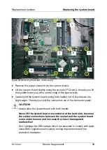
Insert the system board by holding it at a slight angle. Slide the connectors
into the connector panel.
Ê
Lower the system board carefully into the chassis.
Ê
Adjust the system board. If necessary adjust the position of the system
board with a gentle twisting motion.
I
When the system board is in the right position, the centre rings engage
with the holes indicated. The centre rings are placed under the screw
positions 1 and 5.
Ê
Fasten the system board with the eleven screws.
Ê
Reconnect the cables to their original connectors (see also the cabling plans
in the Options Guide).
V
CAUTION!
The power plug P10 is not used. If you connect this power plug this may
cause a short-circuit!
Ê
Install the memory modules (for a description see the Options Guide).
Ê
Install the processor (see the
section “Replacing the processor” on
Ê
Install the system fan (see the
section “Replacing the system fan” on
Ê
Install all controllers in their former slots (for a description see the Operating
Manual and Options Guide).

