background image


PTM900 Mainboard Manual


2-2  


1.) Set System Jumpers 


Jumpers are used to select the operation modes for your system. Some 
jumpers on the board have three metal pins with each pin representing a 
different function. A 1 is written besides pin 1 on jumpers with three pins. To 
set a jumper, a black cap containing metal contacts is placed over the 
jumper pin(s) according to the required configuration. A jumper is said to be 

shorted 

when the black cap has been placed on one or two of its pins. 


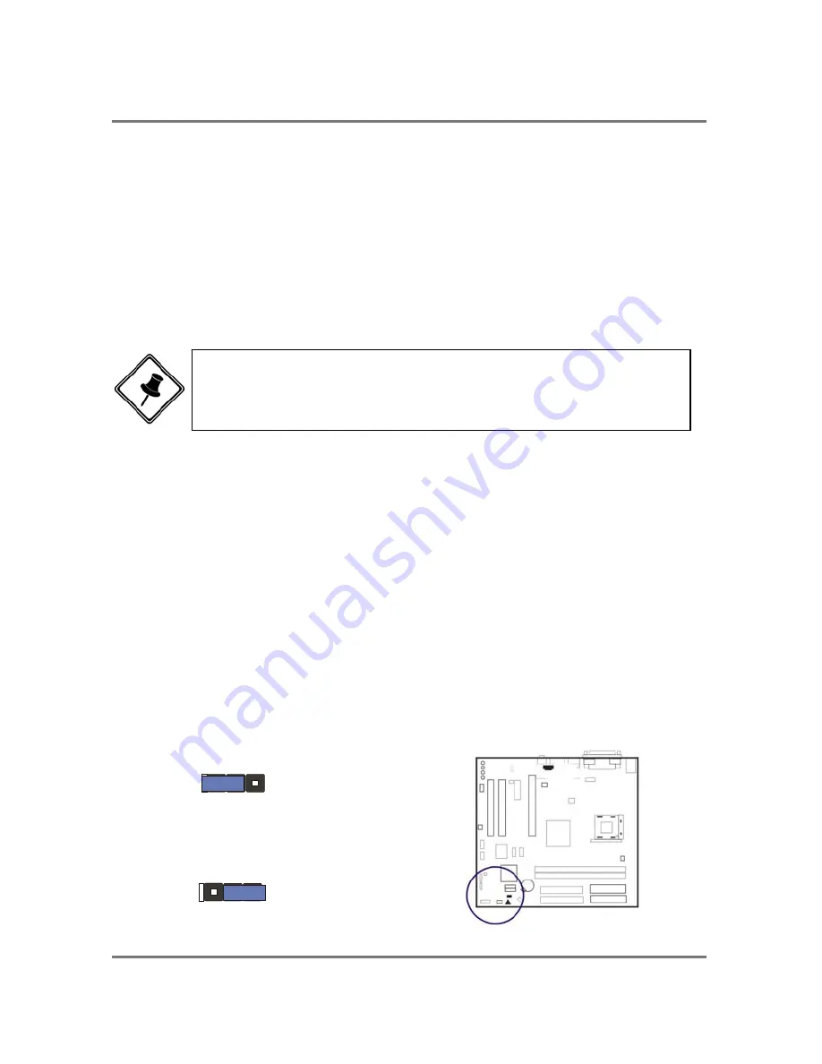
Clear CMOS 

The CMOS RAM is powered by the onboard button cell battery.   
To clear the RTC data:   

(1) 

Turn off your computer;   

(2) 

Open the system case and disconnect the ATX power cable;   

(3)    Place the jumper cap onto the pinpair 2-3 for at least 6 seconds   
 

to enable CMOS clearance;   

(4)    Place the jumper cap onto the pinpair 1-2 to disable the effect of   
 CMOS 

clearance; 


(5)    Connect the ATX power cable and close the system case;   
(6)    Turn on your computer until CMOS checksum error appears;   
(7)    Hold down the Delete key as it boots;   
(8)    Enter the BIOS Setup to re-enter user preferences. 

1  2  3

1  2  3

Normal
(Default)

Enable

(Clear CMOS)


NOTE: Users are not encouraged to change the jumper settings 
that is not listed in this manual. Changing the jumper settings 
improperly may adversely affect system performance. 

Summary of Contents for PTM900

Page 1: ...PTM900 MAINBOARD MANUAL DOC No M0590040 Rev A0 Date 12 2006 Part No 25 13031 00 ...

Page 2: ...PTM900 Mainboard Manual 1 2 This page is intended to be blank ...

Page 3: ...l Expansion Cards 2 6 5 Connect Devices 2 7 Floppy Diskette Drive Connector 2 7 IDE Device Connectors 2 8 Fan Connectors 2 8 Power Connectors 2 9 Front Panel Block Power LED and Speaker Connector 2 10 CD _In Connectors 2 11 Serial ATA Connectors 2 11 Types of Rear Panel I O Connectors 2 12 PS 2 Keyboard and Mouse Connector 2 12 RJ45 LAN Connector 2 12 CRT Connector 2 13 Printer Connector 2 13 Seri...

Page 4: ...1 Standard CMOS Setup 3 2 Advanced BIOS Features 3 4 Advanced Chipset Features 3 5 Integrated Peripherals 3 6 VIA OnChip IDE Device 3 6 VIA OnChip PCI Device 3 7 SuperIO Device 3 8 USB Device Setting 3 9 Power Management Setup 10 PC Health Status 11 Frequency Voltage Control 3 12 Load Optimized Defaults 3 13 Supervisor User Password 3 13 Save and Exit Setup 3 13 Exit without Saving 3 13 ...

Page 5: ...PTM900 Mainboard Manual 1 3 Chapter 1 Overview The PTM900 Mainboard ...

Page 6: ...upport Chipset North Bridge VIA P4M900 South Bridge VIA VT8237A Memory 2 Memory Sockets Support DDRII 400 533 667 MHz total Memory Size up to 2 GBs Expansion Slots 1 PCIe 16 1 PCIe 1 2 PCI Slots IDE Connections 2 IDE Connectors PIO Mode Ultra DMA 66 100 133 Up to 4 Devices SATA Connections 2x SATA with RAID0 1 JBOD Audio Features High Definition Audio 2 Channels Realtek ALC 260 or ...

Page 7: ... Center Sub 8CH LAN Realtek 8100C 10 100 Mbps Lan support or Pin Hearders or Internal Connectors 2 x USB 2 0 pin header 4 outputs 1 x ATX Power connecotor 24pin 1 x ATX 12V Power connecotor 4pin 1 x Front Panel aoudio pin header 1 x CD in audio connecotor 1 x Power LED pin header 1 x Speaker pin header Optional 1 x Serial port pin header Optional 1 x Chassis Intrusion pin header Optional Mounting ...

Page 8: ...PTM900 Mainboard Manual 1 6 This page is intended to be blank ...

Page 9: ...ep 7 Install supporting software tools WARNING Excessive torque may damage the mainboard When using an electric screwdriver on the mainboard make sure that the torque is set to the allowable range of 5 0 8 0kg cm Mainboard components contain very delicate Integrated Circuit IC chips To prevent static electricity from harming any of the sensitive components you should follow the following precautio...

Page 10: ...oard button cell battery To clear the RTC data 1 Turn off your computer 2 Open the system case and disconnect the ATX power cable 3 Place the jumper cap onto the pinpair 2 3 for at least 6 seconds to enable CMOS clearance 4 Place the jumper cap onto the pinpair 1 2 to disable the effect of CMOS clearance 5 Connect the ATX power cable and close the system case 6 Turn on your computer until CMOS che...

Page 11: ...BIOS Setup Screen Users can adjust the frequency through Frequency Voltage Control of the BIOS Setup Screen The procedures below show you how to install your CPU and its fan and heatsink First of all locate the CPU socket on this mainboard 2 Install DDRII DIMM straight down into the socket 1 using both hands then socket 2 1 Locate DDRII DIMM sockets on the mainboard 3 The clip on both ends of the ...

Page 12: ...facturer website 3 Place the fan with heatsink on the CPU top and press down two plastic clips to hook up with the holes on the retention module 1 Swing the lever upward to 90 degree 2 Install the CPU and make sure the pin 1 orientation by aligning the socket corner marking with the socket corner closest to the lever tip Do not insert the CPU by force Make sure the processor is fully inserted into...

Page 13: ...ctor The plug from the power supply will only insert in one orientation because of the different hole sizes Find the proper orientation and push down firmly making sure that the pins are aligned NOTE 1 Insert the CPU with fansink and retention module on socket 2 Connect the 4 pin plug of the power supply 3 Connect the 24 pin plug of the power supply To remove the processor please do it in reverse ...

Page 14: ... bus expansion slots 1 Select an available expansion slot 2 Remove the corresponding slot cover from the computer chassis Unscrew the mounting screw that secures the slot cover and pull the slot cover out from the computer chassis Keep the slot cover mounting screw nearby CAUTION 1 Make sure to unplug the power supply when adding or removing expansion cards or other system components Failure to do...

Page 15: ...ted inside the expansion slot Secure the card with the screw that was removed in Step2 5 Connect Devices Floppy Diskette Drive Connector This connector provides the connection with your floppy disk drive Insert the floppy ribbon cable below onto the floppy connector The colored stripe indicated by the arrow head right of the ribbon cable must be the same side with the Pin 1 ...

Page 16: ... Insert the IDE ribbon cable below onto the IDE connector The colored stripe indicated by the arrow head right of the ribbon cable must be the same side as Pin 1 Fan Connectors The two connectors CPU_FAN and SYS_FAN are linked to the CPU fan and case fan respectively PWR_FAN can be used with the power supply cooling fan Pin1 is GND Pin2 is 12V Pin3 is Signal PWR_FAN Pin3 is no use ...

Page 17: ...ly The 4 pin male block connector is for the ATX_12V power use Both connectors are linked with your ATX power supply The plug from the power supply can only be inserted in one orientation because of the different hole sizes Find the proper orientation and push down firmly making sure that the pins are aligned 24 ...

Page 18: ... speaker and LEDs The plug wires below polarities of these buttons will not affect the function 1 Reset Switch is connected to the reset button Push this switch to reboot the system instead of turning the power button off and on 2 HDD LED is connected to the IDE device indicator This LED will blink when the hard disk drives are activated 3 Power Single and Dual Sleep LED Please refer to the tables...

Page 19: ...OM drive audio analog input use The pin assignment are Pin 1 is Left Pin2 and 3 are GND Pin 4 is Right Serial ATA Connectors The 2 SATA connectors provide you with the connections to serial ATA devices that confirm to the Serial ATA specification Serial ATA supports all ATA and ATAPI devices The figures below left are two SATA cables the top one is for power the next one is for data The data cable...

Page 20: ...s The rear panel I O connectors PS 2 Keyboard and Mouse Connector These two 6 pin female connectors keyboard is purple and mouse is green are used for your PS 2 keyboard and PS 2 mouse RJ45 LAN Connector The RJ45 jack of the LAN port is used for the LAN cable plug ...

Page 21: ...Manual 2 13 CRT Connector This connector is linked to your monitor The pinheaders pin assignments are shown at right side Printer Connector This burgundy colored 25 pin D Sub female connector is attached to your printer ...

Page 22: ...ime can be connected to headphones or preferably powered speakers LINE_IN light blue allows tape players or other audio sources to be recorded by your computer or played through the LINE_OUT MIC_IN pink allows microphones to be connected for audio input CES Subwoofer Orange can be connected to the center subwoofer speaker Rear black can be connected to the rear speaker Side grey can be connected t...

Page 23: ...us Connectors The mainboard has eight USB ports four USB black jacks that are integrated on the edge of the board and four other USB ports pinheaders on the board They allow users to attach to USB devices either from the rear or front panels Please note that your operating system must support USB 1 1 2 0 features NOTE If you do not use F_AUDIO please keep the pinpair 5 6 9 10 short as default also...

Page 24: ...PTM900 Mainboard Manual 2 16 The figure at right shows the pin assignments of the USB5 6 Those of USB7 8 are similar ...

Page 25: ...PTM900 Mainboard Manual 2 17 This page is intended to be blank ...

Page 26: ......

Page 27: ...n the Setup program and tells you how to modify the settings according to your system configuration CMOS Setup Utility The Setup utility program allows updates to the mainboard configuration settings The BIOS setup values will be saved in the CMOS It is executed when the user changes system configuration user changes system backup battery or the system detects a configuration error and asks the us...

Page 28: ...To set the date highlight the Date field and then press Page Up Page Down or keys to set the current date Follow the month day and year format Time To set the time highlight the Time field and then press Page Up Page Down or keys to set the current time Follow the hour minute and second format Hard Disks This field records the specifications for all non SCSI hard drives installed in the system The...

Page 29: ...sk drive changes the write current Landing Zone The cylinder number on which the disk drive heads read write are seated when the disk drive is parked Sector The sector number of each track defined on the hard disk Drive A This field records the types of floppy drives installed in the system To enter the configuration value for a particular drive highlight its corresponding field and then select th...

Page 30: ... Threading Technology This feature allows user to enable or disable the Hyper Threading Technology The options are Enabled Disabled First Second Third Boot Device This feature allows user to select the boot device priority The options are Floppy LS120 Hard Disk CDROM ZIP100 USB FDD USB ZIP USB CDROM LAN Disabled Boot Other Device This feature allows user to select the boot device priority The opti...

Page 31: ...ptions Setup System Advanced Chipset Features AGP Aperture Size It allows you to select the main memory frame size for AGP use The options list presents all provided possibilities VGA Share Memory Size This feature allows you to select the size in the VGA shared memory The options are 32M 64M 128M ...

Page 32: ...PTM900 Mainboard Manual 3 6 Integrated Peripherals VIA OnChip IDE Device ...

Page 33: ...SATA controller mode The options are IDE Raid OnChip IDE Channel0 This item allows users to enable or disable the IDE Channel 0 function though the system will auto detect this device The options are Enabled Disabled OnChip IDE Channel1 This item allows users to enable or disable the IDE Channel 1 function though the system will auto detect this device The options are Enabled Disabled VIA OnChip P...

Page 34: ... disable the onboard LAN device The options are Enabled Disabled Onboard Lan Boot ROM This feature allows users to enable or disable the onboard Lan boot ROM to boot system The options are Enabled Disabled SuperIO Device Onboard Serial Port 1 If the serial port 1 uses the onboard I O controller you can modify your serial port parameters The options are 3F8 IRQ4 3E8 IRQ4 2F8 IRQ3 2E8 IRQ3 Disabled ...

Page 35: ...rts The options are SPP EPP ECP ECP EPP ECP Mode Use DMA This feature allows you to select Direct Memory Access DMA channel if the ECP mode selected The options are 1 3 USB Device Setting USB1 0 Controller Disable this option if you are not using the onboard USB 1 1 feature The options are Disabled Enabled USB2 0 Controller Disable this option if you are not using the onboard USB 2 0 feature USB 1...

Page 36: ...wing to the power failure the system itself will not be back to power on This feature allows you to set the system back to the previous power status when the system is resumed The options are Off On Former STS USB Resume From S3 This option determines to activate or inactive the USB function when the system resumes from S3 RTC Alarm Resume This option lets you set up the time to activate the syste...

Page 37: ... disable the High Precision Event Timers function The options are Disabled Enabled HPET Mode This option lets you set up the High Precision Event Timers mode The options are 32 bit 64 bit PC Health Status Vcore 3 3V 5V 12V CPU Temperature System Temperature CPU FAN System FAN These items allow end users and technicians to monitor data provided by the BIOS on this mainboard It is not user configura...

Page 38: ...ns are 15X 16X 17X depent on CPU type Spread Spectrum This feature allows users to select the range of spread spectrum The options are Disabled 1 50 1 00 0 70 0 50 0 75 0 50 0 35 0 25 Auto Detect PCI Clk When enabled BIOS will detect the PCI slot and DIMM slot If no any device in BIOS will auto disable its clock The options are Enabled Disabled ...

Page 39: ...rompted password every time you try to enter the CMOS Setup Utility If System is selected and the Supervisor User Password is enabled you will be requested to enter the Password every time when you reboot the system or enter the CMOS Setup utility Save and Exit Setup After you have made changes under Setup press Esc to return to the main menu Move cursor to Save and Exit Setup or press F10 and the...

Page 40: ...PTM900 Mainboard Manual 3 14 This page is intended to be blank ...

Reviews: