background image

Summary of Contents for ScanParter 10C

Page 1: ...ScanPartner 10C Image Scanner User s Manual ...

Page 2: ...RANTEE THAT INTERFERENCE WILL NOT OCCUR IN A PARTICULAR INSTALLATION IF THIS EQUIPMENT DOES CAUSE HARMFUL INTERFERENCE TO RADIO OR TELEVISION RECEPTION WHICH CAN BE DETERMINED BY TURNING THE EQUIPMENT OFF AND ON THE USER IS ENCOURAGED TO ATTEMPT TO CORRECT THE INTERFERENCE BY ONE OR MORE OF THE FOLLOWING MEASURES REORIENT OR RELOCATE THE RECEIVINGANTENNA INCREASE THE SEPARATION BETWEEN THE EQUIPME...

Page 3: ...10 Image Scanner User s Manual TABLE OF CONTENTS Chapter 1 General 3 Chapter 2 Scanner Installation 3 Chapter 3 Operation 14 Chapter 4 Replacement of Lamp Units 19 Chapter 5 Paper Jams 28 Chapter 6 Diagnostics 31 2 ...

Page 4: ...p size l Built in Automatic Document Feeder ADF of 50 page capacity CHAPTER 2 SCANNER INSTALLATIDN 2 1 Selecting a Location Follow these precautions when l Avoid locations where l Avoid direct sunlight selecting an installation site for the scanner excess vibration may occur l Avoid excessive humidity and dust l Use the proper AC power source 2 2 Unpacking Procedure Unpack the scanner according 1 ...

Page 5: ... FOAM LEFl Figure 2 1 Parts in the package 4 ...

Page 6: ...position 2 4 Automatic Dtiument Feeder ADF ADF Input Paper Chute Raise the unattached end of the input paper chute about 45 as 2 4 1 1 2 3 4 2 4 2 1 2 3 4 2 5 shown in Figure 2 3 Pull the metal bracket down from the Slide the metal bracket into the grips Pull the chute extension up as far as ADF Output Paper Stacker under side of the paper chute on the document cover possible Position the output p...

Page 7: ... Figure 2 2a Remove the shipping retainer Figure 2 2b Fasten the shipping retainer 6 ...

Page 8: ... Figure 2 3 Set up the ADF input paper chute 7 ...

Page 9: ...rExtensions Extensions 2 Figure 2 4 Set up the ADF output paper stacker 8 ...

Page 10: ...r ADF chute Figure 2 5 ScanPartner 10 Image Scanner With ADF output paper stacker lent Figure 2 6 ScanPartner 10 Image Scanner Without ADF output paper stacker 9 cover ...

Page 11: ...ser can buy the SCSI cable in the computer stores The specifications of the SCSI cable is as below Name SCSI Cable Cable Specification 50 pins to 50 pins shielded Cable Length less than or equal to 6 meters SCSI Cable Connection There are two configurations for the connections Configuration I The number of devices attached to the SCSI bus including the host PC is three or above And the scanner is ...

Page 12: ...ctor Plug one end of the SCSI cable into the FEMALE side of the terminator and the other end of the cable to one female connector of the previous device or the host spacifications requires that Only one terminator may be attached to each end of the daisy chain The total length of the daisy chain must not exceed 6 meters The vendor suggests that the SCSI cable be two or three meters in length to al...

Page 13: ...Power Cable Figure 2 7 Power cable connection 12 ...

Page 14: ...Figure 2 8 Signal cable connection 13 ...

Page 15: ...ator intervention The ADF mode is particularly useful when multiple sheets are being scanned The following two subsections describe the operation of each scanning mode 3 2 1 1 2 3 4 5 6 3 2 2 1 2 3 4 5 Ftat Bed Open the document cover Place the document face down on the documenit board with the top edge towards the scan aperture as shown in Figure 3 2 Position the document so that its left side an...

Page 16: ...Power switch Figure 3 1 Power on 15 ...

Page 17: ...Figure 3 2 Flat bed scanning I 16 ...

Page 18: ...Flgure 3 3 Flat bed scanning II 17 ...

Page 19: ...Figure 3 4 ADF scanning 18 ...

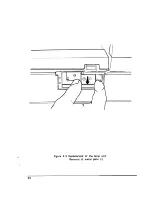
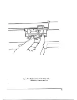
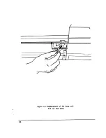
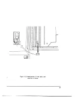
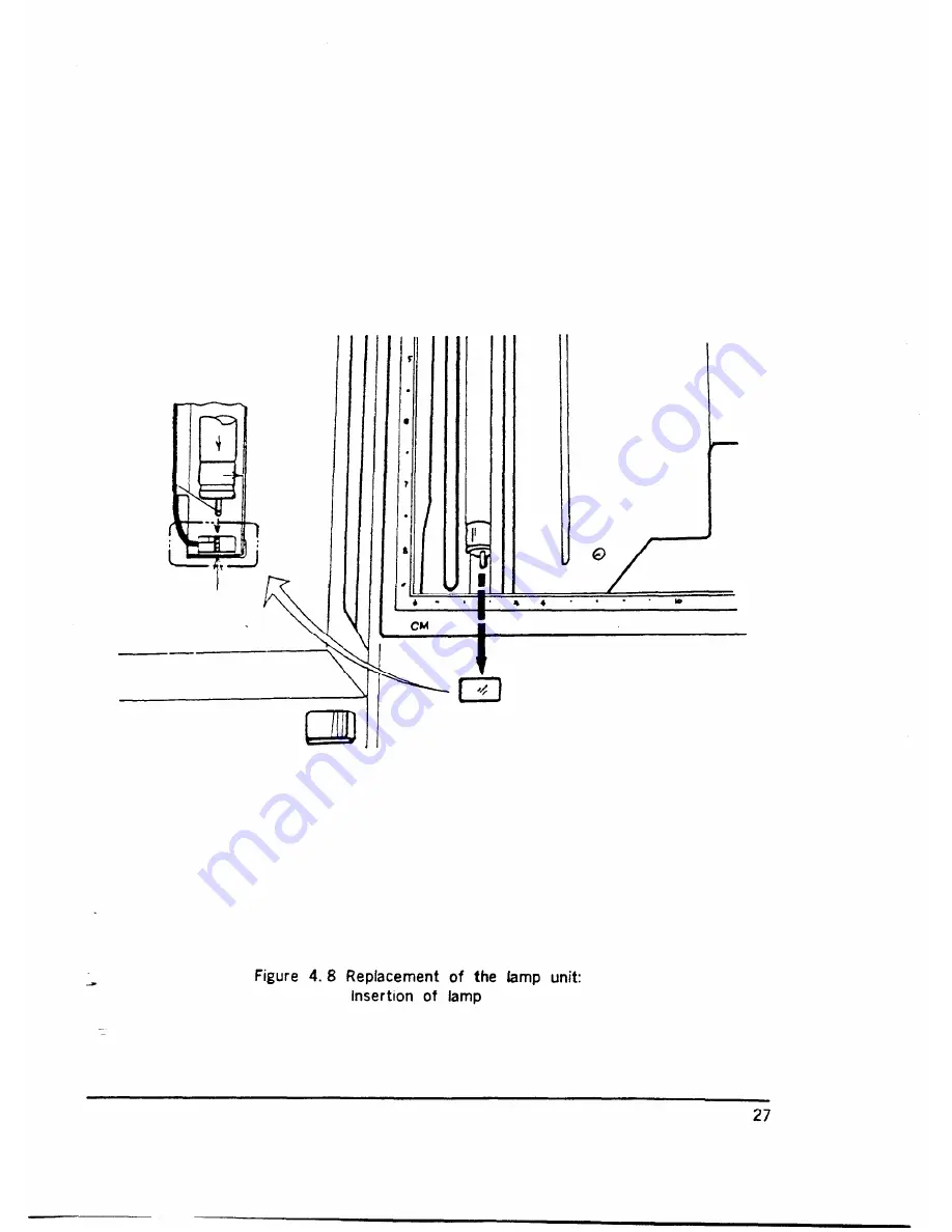
Page 20: ... shown in Figure 4 4 Remove the metal plate as shown in Figure 4 5 and 4 6 Remove the lamp from the scanner by pulling it straight out If the lamp is difficult to remove use pliers to remove it as shown in Figure 4 7 4 2 Installing the New Lamp 1 Insert the new lamp into the lamp holder inside the scanner The lamp can be seen through the document glass Position the lamp so that the two pins are ve...

Page 21: ...Figure 4 1 Replacement of the lamp unit Take out the spare lamp 20 ...

Page 22: ...Figure 4 2 Replacement of the lamp unit Remove the screw 21 ...

Page 23: ...Figure 4 3 Replacement of the lamp unit Remove the lamp holder cover 22 ...

Page 24: ...Figure 4 4 Replacement of the lamp unit scroll Out the copper bar 23 ...

Page 25: ...Figure 4 5 Replacement of the lamp unit Removal of metal plate I 24 ...

Page 26: ...Figure 4 6 Replacement of the lamp unit Removal of metal plate II 25 ...

Page 27: ...Figure 4 7 Replacement of the bmp unit Pull out that bmp 26 ...

Page 28: ...Figure 4 8 Replacement of the lamp unit insertion of lamp 27 ...

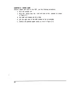
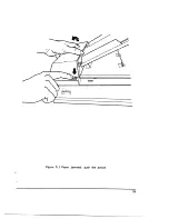
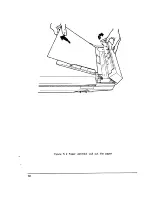
Page 29: ...g procedures 1 Turn the scanner off 2 Push the botton near the front left side of the scanner as shown in Figure 5 1 3 The ADF unit module will lift a little 4 Lift the right side of the ADF module as far as possible 5 Remove the jammed paper slowly as show in Figure 5 2 28 ...

Page 30: ...Figure 5 1 Paper Jammed push the botton 29 ...

Page 31: ...Figure 5 2 Paper Jammed pull out the paper 30 ...

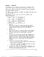
Page 32: ...opening the ADF cover and closing it Power off and then power on the scanner again If this condition still exists please contact your nearest dealer or distributer Lamp Fail This error means that the lamp being used may be burned out or the light is too dark due to aging Please refer to Chapter 4 for replacing the new lamp If necessary please contact your nearest dealer for a new lamp If the error...

Reviews: