SK-91465X-100PMC User Guide
Chapter 3 Jumpers and Switches
© Fujitsu Microelectronics Europe GmbH
- 15 -
UG-910056-11
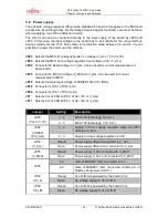
Jumper
Setting
Description
1 - 2
Vcc of CAN A is supplied with 5V
JP1
(CAN A Vcc)
2 - 3
Vcc of CAN A is supplied with V_ALL
1 - 2
Vcc of CAN B is supplied with 5V
JP11
(CAN B Vcc)
2 - 3
Vcc of CAN B is supplied with V_ALL
Default: grey
Table 3-2: Power supply jumper settings
Power measurements:
Via JP52 it is possible to measure the power consumption of the whole board.
Via JP55 the consumption of MCU Vcc pins can be measured.
For VDD5R consumption measurements JP64 must be used.
3.2.1 Power switching by FlexRay physical layer
This board supports power switching by FlexRay physical layer (X9, X11).
For this reason the Vcc voltage (Selected by JP63) is controlled by a MOSFET (Q2).
12V level at the Gate pin will pass the Vcc voltage to the board. Connecting 0V at the Gate
pin the MOSFET (Q2) switch off the Vcc power supply of the board.
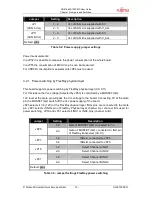
JP25 selects if Vin (12V) or the FlexRay physical layer INHx pins are connected to the Gate
pin. JP27 selects if INHx pin of FlexRay Physical layer channel A or channel B is used for
power switching. JP19 and JP31 selects if INH1 or INH2 pins (channel A / B).
Jumper
Setting
Description
1-2
Gate of MOSFET (Q2) connected to Vin
JP25
2-3
Gate of MOSFET (Q2) connected to INH pin
of FlexRay transceiver (X9, X1)
1-2
INHx-A connected to JP25
JP27
3-4
INHx-B connected to JP25
1-2
Select Channel A INH1
JP19
2-3
Select Channel A INH2
1-2
Select Channel B INH1
JP31
2-3
Select Channel B INH2
Default: grey
Table 3-3: Jumper Settings FlexRay power switching


