SK-91465X-100PMC User Guide
Chapter 3 Jumpers and Switches
UG-910056-11
- 22 -
© Fujitsu Microelectronics Europe GmbH
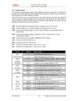
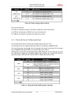
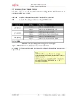
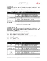
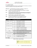
3.11 Reset-Generation
In addition to the internal Power-On reset, the microcontroller can be reset by an external
reset circuit (Voltage Monitor) and also by a RS232 interface.
JP28, 50, 71 As well the DTR-line as the RTS-Line of UART”A” or UART “B” or
UART “C”can be used to generate a system reset.
JP72
This jumper selects whether the DTR/RTS line from UART”A” or UART”B”
or UART “C”will generate a system reset.
JP13
This solder jumper selects between normal (immediate) reset and delayed reset.
In delayed reset mode, the reset button has to be held down for 2 sec before a
reset is generated to avoid accidental resets.
JP14
Open this jumper if no external Reset shall be generated.
In this case only the internal reset is active (e.g.: power-on)
JP33
The signal on the DTR/RTS line can be negated with this jumper.
Remove the jumper in order to disable the RS232 reset circuit.
Jumper
Setting
Description
1-2
DTR of UART”A” is selected
JP28 (DTR / RTS “A”)
2-3
RTS of UART”A” is selected
1-2
DTR of UART”B” is selected
JP50 (DTR / RTS “B”)
2-3
RTS of UART”B” is selected
1-2
DTR of UART”C” is selected
JP71 (DTR / RTS “C”)
2-3
RTS of UART”C” is selected
1-2
UART”A” is used to generate Reset
3-4
UART”B” is used to generate Reset
JP72 (UART”A”/”B/C”)
5-6
UART”C” is used to generate Reset
1-2
Reset is applied immediately when SW6 is pressed
JP13
(Reset imm./delayed)
2-3
Reset is applied when SW6 is pressed >2sec
Closed
External Reset generation is active
JP14 (Main Reset)
Open
No external Reset generation
1-2
No negation for the DTR/RTS signal
JP33 (Polarity)
2-3
DTR/RTS signal is negated
Default: grey
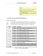
Table 3-12: Reset Jumper Settings
Note 1:
JP28, JP33, JP50, JP71 and JP72 default setting is
open.


