background image

SK-96380-120PMT User Guide 

 Chapter 6 Getting Started 

© Fujitsu Microelectronics Europe GmbH 

- 29 -  

FMEMCU-UG-960001-15 

6 Getting Started 

Make sure that the 16LX/FX Family Softune Workbench is installed on your PC and the “SK-
96380-120PMT” is ready to use (power-on, serial connection UART0) to a COM port of the 
PC).  


6.1  Introduction to Softune Workbench 

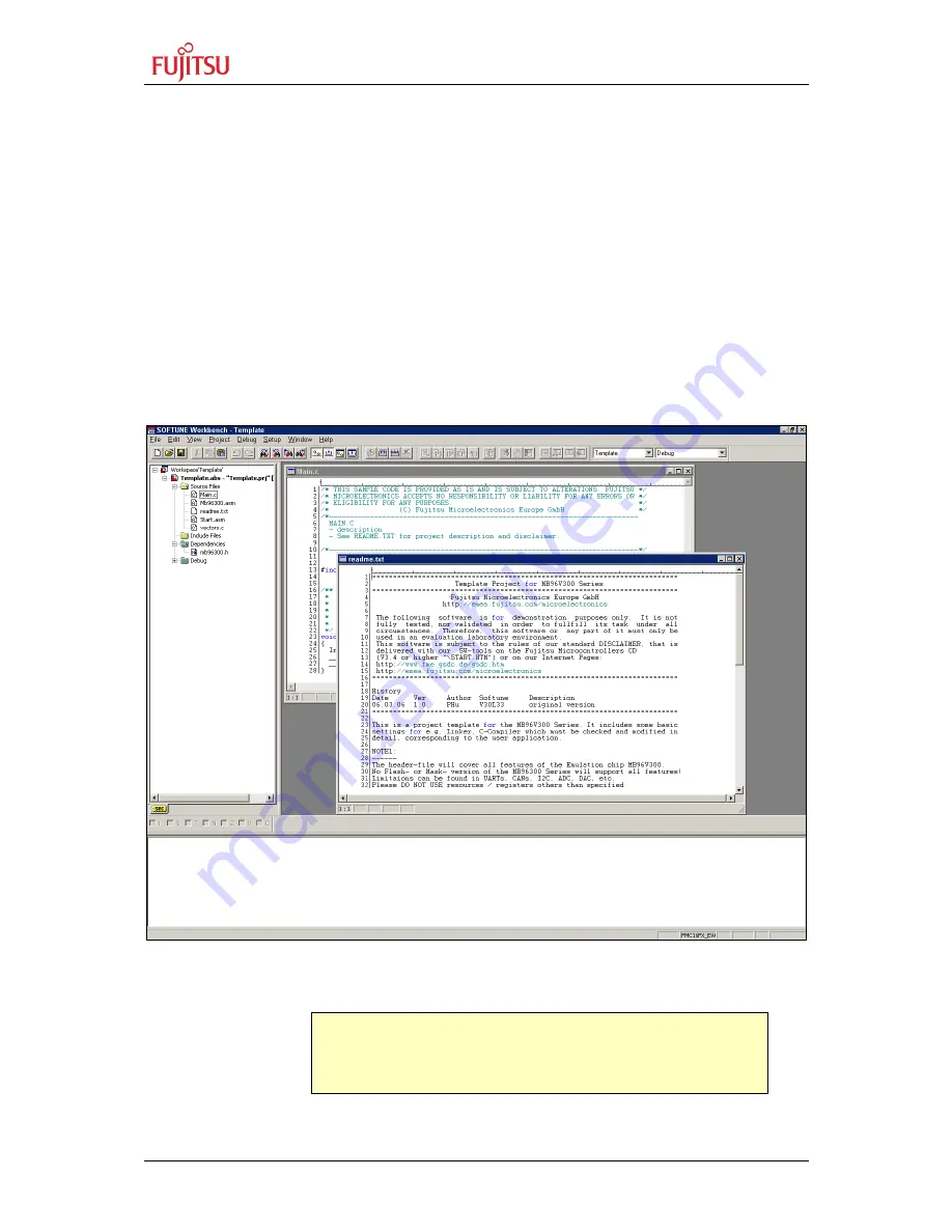
Start Softune Workbench. Select <File> <Open Workspace> to load the first example. (e.g. 

mb96380_io.wsp

). All examples can be found in the folder \Software\SWB_Samples on the 

starter-kit DVD-ROM. It is recommended to copy this folder to the local hard-drive. In the 
project tree on the left side, you can open the “source”-folder which contains the source-files 
registered to this project. A double-click on one of the files will invoke the built-in editor, 
which supports syntax-highlighting, tags, and various other functions. 

Figure 6-1: Softune Workbench main window 


Note: 


You may customize the editor by a right-click on the editor 
window. 

Summary of Contents for SK-96380-120PMT

Page 1: ...Fujitsu Microelectronics Europe User Guide FMEMCU UG 960001 15 MB96300 SERIES EVALUATION BOARD SK 96380 120PMT V1 0 USER GUIDE ...

Page 2: ...te Issue 2006 07 04 V1 0 MWi Initial version 2006 09 18 V1 1 PHu misc corrections 2006 10 19 V1 2 MWi Jumper settings updated 2006 10 20 V1 3 MWi External Bus Interface is not released for SK 96380 120PMT V1 0 2006 11 27 V1 4 CSc Socket Note added 2007 03 02 V1 5 HWe DGo Recycling Note added This document contains 41 pages ...

Page 3: ...om the date of receipt by the customer 2 Should a Product turn out to be defect Fujitsu Microelectronics Europe GmbH s entire liability and the customer s exclusive remedy shall be at Fujitsu Microelectronics Europe GmbH s sole discretion either return of the purchase price and the license fee or replacement of the Product or parts thereof if the Product is returned to Fujitsu Microelectronics Eur...

Page 4: ...22 42 16 3 3 Analog Power Supply Voltage JP 11 12 13 14 17 3 4 LIN UART Connectors X5 and X9 18 3 5 CAN interfaces X6 and X8 20 3 6 Reset Generation JP 32 33 41 48 20 3 7 User Buttons SW1 SW2 SW3 SW4 SW5 SW6 JP 3 4 5 6 and 7 22 4 CONNECTORS 23 4 1 Power connector X7 23 4 2 MCU pin header connectors X1 and X2 23 4 3 LIN UART connectors X5 X9 23 4 4 CAN Connector X6 X8 24 4 5 USER LEDs optional LC D...

Page 5: ...ND Connector J8 27 5 POTENTIOMETERS 28 5 1 RP1 28 5 2 RP2 28 6 GETTING STARTED 29 6 1 Introduction to Softune Workbench 29 6 2 Project Start up 31 7 PROGRAMMING THE INTERNAL FLASH MEMORY 34 7 1 Asynchronous Mode 34 7 2 Synchronous Mode 36 8 APPENDIX 37 8 1 Related Products 37 8 2 Information in the WWW 38 8 3 Tables 39 8 4 Figures 40 8 5 Abbreviations 41 ...

Page 6: ...0PMT is a multifunctional evaluation board for the Fujitsu 16FX Flash microcontroller series MB96F38x It can be used stand alone for software development and testing or as a simple target board to work with the emulator system The board allows the designer immediately to start software development before his own final target system is available ...

Page 7: ...voltages Onboard voltage supervisor monitors three of four supply voltages In Circuit serial Flash programming UART0 or UART2 All resources available for evaluation All MCU pins routed to connectors 4 MHz main crystal 32 kHz crystal for sub clock operation 2 RS232 or LIN interfaces and 2 CAN interfaces are usable simultaneously 3 V capable CAN LIN and RS232 transceivers 8 User LEDs optional alphan...

Page 8: ...ceivers are fully 3 3V IO compatible to enable low voltage applications In circuit programming asynchronous can be done via LIN UART 0 and 2 X5 X9 1 3 3 CAN Bus Two high speed CAN transceivers TLE6250GV33 can be connected to the CAN interfaces of the MCU to allow easy connection to CAN networks All transceivers are fully 3 3V IO compatible to enable low voltage applications 1 3 4 MCU Pins All pins...

Page 9: ...d to the I C bus lines by setting the according Jumpers JP9 is for SDA0 and JP10 for SCL0 1 3 9 Emulator System If the board is used as an emulator target board the microcontroller must be removed from the socket and the corresponding probe cable has to be mounted Table 1 1 Emulation System Series V Chip Probe cable Socket MB96380 MB96V300 MB2198 16FX 120P M21 NQPack120SD ...

Page 10: ...rocontroller from the socket Now the probe cable can be mounted on the socket Take care of the pin 1 marking on the socket and fasten the probe cable with the provided screws Do not use any other probe cable than MB2198 16FX 120P M21 only Connect the probe cable to the MB2198 500 emulation Adapter Board Check all jumper settings of the evaluation board the Probe Cable and the Adapter Board When tu...

Page 11: ...5V selection for DVCC Jumper 3 pin 2 3 K 12 JP18 DVSS connection Jumper 2 pin Closed K 12 JP19 CTS RTS UART0 Jumper 2 pin Closed I 3 JP20 VCC5V VCC CAN0 Transceiver Solder JP 3 pin 1 2 D 4 JP21 RS232 LIN SIN0 UART0 Jumper 3 pin 1 2 H 5 JP22 Mains Switch Jumper 2 pin Open L 17 JP23 DTR RTS UART0 selection Jumper 3 pin Open I 3 JP24 CAN0 RxD connection Jumper 2 pin Closed E 4 JP25 RS232 LIN SOT0 UAR...

Page 12: ...h Jumper 3 pin Open D 9 JP50 Word Byte access On Board SRAM Jumper 3 pin Open E 9 JP51 BUSMUX selector Jumper 2 pin Open F 16 JP52 Latch A0 A15 On Board Flash Jumper 3 pin Open D 9 JP53 Latch A0 A15 On Board SRAM Jumper 3 pin Open E 9 JP54 A20 VG 96 connector Solder JP 2 pin Open C15 JP55 A23 VG 96 connector Solder JP 2 pin Open C 15 JP56 A21 VG 96 connector Solder JP 2 pin Open C 15 JP57 A22 VG 9...

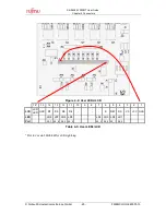
Page 13: ...15 2 3 Jumper Location The following picture shows the silk plot of the starter kit with marked default jumper settings A B C D E F G H I J K L M 1 1 2 2 3 3 4 4 5 5 6 6 7 7 8 8 9 9 10 10 11 11 12 12 13 13 14 14 15 15 16 16 17 17 18 18 19 19 20 20 A B C D E F G H I J K L M Figure 2 1 Default Jumper Settings ...

Page 14: ... are logged in with administrator or poweruser permissions otherwise the Softune Workbench installation will fail Be aware that Softune Workbench does not support multi user support Therefore install and user login must be the same 2 Browse on the starter kit DVD ROM into the directory Micros DVD 4 0 pdf and start the 16STA exe 3 Follow the installation instructions 4 For the default installation ...

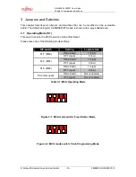
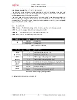
Page 15: ...e default setting for the MB96F387 Series is shown with a grey shaded area 3 1 Operating Mode S1 This switch controls the MCU operation mode after Reset Please take care of the following mode settings DIP switch Setting Logical value ON closed 1 high S1 1 MD0 OFF open 0 low ON closed 1 high S1 2 MD1 OFF open 0 low ON closed 1 high S1 3 MD2 OFF open 0 low ON closed Not connected S1 4 Not used OFF o...

Page 16: ...s not possible to power the board over the LIN bus S2 Power Switch JP16 Connects the MCU IO voltage to Vcc It can be used for current measurement JP17 Selects the Stepper Motor Driver Voltage 3 3V or 5V JP28 42 Connects VBat Pin 1 of D Sub Connector to Vs JP22 Mains jumper overrides the power switch S2 Switch Setting Description ON 1 2 Power ON S2 OFF 2 3 Power OFF Table 3 2 Power Switch Jumper Se...

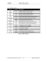
Page 17: ...ted from Vcc Closed AVRH is connected to AVcc JP12 AVRH Open AVRH defined by resistor network 1 Closed AVRL is connected to AVss JP13 AVRL Open AVRL defined by resistor network 1 Closed AVss is connected to GND JP14 AVss Open AVss is disconnected from GND 1 By default the resistor network R16 R17 R20 R21 is not mounted on the board Table 3 4 ADC Supply Default JP11 JP12 JP13 and JP14 are closed By...

Page 18: ...only a protection diode between Vin and Vs 3 4 1 LIN UART 0 X5 Jumper Setting Description 1 2 SIN0 is connected to RS232 transceiver JP21 RXD 2 3 SIN0 is connected to LIN transceiver 1 2 SOT0 is connected to RS232 transceiver JP25 TXD 2 3 SOT0 is connected to LIN transceiver 1 2 X5 Pin2 is connected to RS232 transceiver T1out JP27 RS232 LIN 2 3 X5 Pin2 is connected to LIN transceiver BUS Closed RT...

Page 19: ...nsceiver T1out JP40 RS232 LIN 2 3 X9 Pin2 is connected to LIN transceiver BUS Closed RTS and CTS of X9 are connected JP36 RTS CTS Open RTS and CTS of X9 are not connected 1 2 DTR signal Pin 6 of X9 is used as reset source JP38 DTR RTS 2 3 RTS signal Pin 7 of X9 is used as reset source Closed LIN transceiver for X5 is enabled JP43 LIN enable Open LIN transceiver for X5 is disabled Closed LIN UART2 ...

Page 20: ...rs X5 or X9 for DTR RTS selection JP33 Selects X5 or X9 as reset source JP41 The signal on the DTR RTS line can be negated with this jumper Remove the jumper in order to disable the RS232 reset circuit JP46 With this jumper the time to hold down reset button SW6 controlled JP48 Open this jumper if no external Reset shall be generated In this case only the internal reset is active e g power on Jump...

Page 21: ...set signal is asserted the red Reset LED LD13 is lit During normal operation this LED should be off If JP41 DTR DTRx is set the UART RESET jumper JP33 and the according DTR RTS JP23 and JP38 jumper have to be set too If the reset LED is steadily on check the power supply input voltage and the settings for the reset generation by UART ...

Page 22: ...ction to the microcontroller Closed Pin 77 FRCK0R of the MCU is connected to SW2 JP4 SW2 Open No connection to the microcontroller Closed Pin 80 TIN1R of the MCU is connected to SW3 JP5 SW3 Open No connection to the microcontroller Closed Pin 18 IN0 TTG4 0 of the MCU is connected to SW4 JP6 SW4 Open No connection to the microcontroller Closed Pin 19 IN1 TTG5 1 of the MCU is connected to SW5 JP7 SW...

Page 23: ...connector Pin 2 of the MCU corresponds to Pin 2 of the connector and so on 4 3 LIN UART connectors X5 X9 Two 9 pin D Sub female connectors are used for the serial interfaces Note that X5 and X9 are shared between the RS232 and LIN transceivers and must be configured to the desired functionality refer to chapter 3 4 for details Figure 4 2 UART Connector Pin Number Pin Signal Description 1 VBat Powe...

Page 24: ... input output 8 NC Not used 9 NC Not used Shield GND Ground Table 4 2 CAN Connector Signals 4 5 USER LEDs optional LC Display Eight LEDs are supplied for user applications In order to disconnect the LEDs from the related microcontroller port Port 09 the resistor network RN1 can be removed Instead of the user LEDs an alphanumeric LC Display optional can be connected The potentiometer RP1 can be use...

Page 25: ...bH 25 FMEMCU UG 960001 15 Figure 4 4 User LEDs LCD 16 15 14 13 12 11 10 9 8 7 6 5 4 3 2 1 LCD LCD LED GND D7 D6 D5 D4 E R W RS V0 VCC GND LED LD8 LD7 LD6 LD5 LD4 LD3 LD2 LD1 Port 09_7 09_6 09_5 09_4 09_3 09_2 09_1 09_0 Table 4 3 User LEDs LCD Pin16 Vcc via 39U 0 5W for LCD Lightning ...

Page 26: ...m the flash MCU with a special programming adapter Mode pin MD0 and reset signal are also available at this connector Figure 4 5 In circuit programming connector Pin Number Pin Signal Description 1 NC Not used 2 NC Not used 3 MD0 MCU mode pin 0 4 NC Not used 5 RSTX MCU reset signal 6 SIN2 UART2 receive data 7 SOT2 UART2 transmit data 8 SCK2 UART2 clock 9 VCC Board supply voltage 10 GND Ground Tabl...

Page 27: ...4 9 Vcc 5 Volts J4 On this connector the VCC5V supply can be measured 4 10 Vcc 3 3 Volts J5 On this connector the VCC3V3 supply can be measured 4 11 Vcc 2 5 Volts J9 On this connector the VCC2V5 supply can be measured 4 12 Vcc 1 8 Volts J10 On this connector the VCC1V8 supply can be measured 4 13 LIN Bus Inhibit J6 To this connector the INH pin of the LIN0 transceiver is connected 4 14 LIN Bus Inh...

Page 28: ...RP1 the contrast of a connected alphanumerical LCD board to J1A B can be adjusted 5 2 RP2 With the potentiometer RP2 the threshold voltage for the alarm comparator can be adjusted Any voltage between VCC and GND can be set It is connected to the comparator 0 thus to pin ALARM0 Additionally the adjusted voltage can be measured at connector J2 ...

Page 29: ...en Workspace to load the first example e g mb96380_io wsp All examples can be found in the folder Software SWB_Samples on the starter kit DVD ROM It is recommended to copy this folder to the local hard drive In the project tree on the left side you can open the source folder which contains the source files registered to this project A double click on one of the files will invoke the built in edito...

Page 30: ...ssage No Error will appear If you get any errors during build an appropriate message will be generated Try this with a simple syntax error e g delete a semicolon from the end of a C line and click on MAKE again You will now see a message like this Now Making Configuration mb96380_io prj Debug Main c c work mb90340 reflash_test src main c 19 E4062C syntax error near __set_il Error detected To locat...

Page 31: ...e folder 96380_template vXX and rename the folder to e g my_application 3 Enter the folder my_application Rename mb96380_template prj into my_application prj Rename mb96380_template wsp into my_application wsp 4 Edit my_application prj Replace all mb96380_template entries to my_application 5 Edit my_application wsp Replace all mb96380_template entries to my_application In any case the settings don...

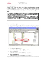
Page 32: ...ed FMEMCU UG 960001 15 32 Fujitsu Microelectronics Europe GmbH 6 Start Softune Workbench and open your project Figure 6 2 Open Softune Workbench workspace wsp Rename mb96380_template into my_application Note that DirInfo entries are not needed to edit ...

Page 33: ... Motorola S Record can be programmed with the flash programming utility into the internal Flash memory Please keep in mind that therefore the mode pins have to be set to Internal ROM Mode Vector Note Always check the memory map of the linker settings and ensure that this memory map is suitable for the application and target system in use Additionally the mp1 file should be checked to ensure correc...

Page 34: ... in automatic mode 1 For serial asynchronous programming SUB D9 connector X5 or X9 which are connected to UART0 and 2 have to be used The following jumper setting is needed Jumper Programming UART Setting Description JP21 SIN0 UART0 1 2 RS232 RxD is connected to SIN0 JP25 SOT0 UART0 1 2 RS232 TxD is connected to SOT0 JP27 RS232 LIN UART0 1 2 RS232 is selected JP28 Vbat UART0 Open Vbat is not conne...

Page 35: ...e UART0 1 2 LIN UART 0 X5 connected to reset circuit JP33 RESET A B UART2 2 3 LIN UART 2 X9 connected to reset circuit 1 2 No negation for the DTR RTS signal JP41 DTR DTRx 2 3 DTR RTS signal is negated 1 2 Reset is applied immediately when SW6 is pressed JP46 Direct RST 2 3 Reset is applied when SW6 is pressed 2sec Table 7 2 Jumper Settings for reset signal 3 The CPU Mode selection must be set to ...

Page 36: ...ication is programmed to the embedded Flash memory Program Verify If the programming sequence has ended successfully you will receive the output It all ended normally completely 7 2 Synchronous Mode In order to program the Flash ROM synchronously special third party soft and hardware has to be used e g GALEP 4 from www conitec de This tool is not available for free A dedicated Flash programming so...

Page 37: ...U in LQFP 120 package MB2198 01 Emulator debugger main unit MB2198 500 Emulation Pod NQPack120SD Socket for package LQFP 120 Tokyo Eletech Corp www tetc co jp e_tet htm HQPack120SB Socket header for package LQFP 120 Tokyo Eletech Corp www tetc co jp e_tet htm MB2198 16FX 120P M21 Emulator probe cable for MB96F38x MCU MB96300 Series MB96V300 MB96300 Series Evaluation chip MB96F38x Flash MCU ...

Page 38: ... 2 Information in the WWW Information about FUJITSU MICROELECTRONICS Products can be found on the following Internet pages http emea fujitsu com microelectronics Microcontrollers 8 16 and 32bit Graphics Controllers Datasheets and Hardware Manuals Support Tools Hard and Software http www fme gsdc de gsdc htm ...

Page 39: ...le 3 3 Power Supply Configuration 16 Table 3 4 ADC Supply 17 Table 3 5 UART0 Settings 18 Table 3 6 UART2 Settings 19 Table 3 7 CAN Settings 20 Table 3 8 Reset Connection 20 Table 3 9 User Push Buttons 22 Table 4 1 UART Connector Signals 23 Table 4 2 CAN Connector Signals 24 Table 4 3 User LEDs LCD 25 Table 4 4 In circuit programming connector 26 Table 7 1 Jumper Settings for Programming 34 Table 7...

Page 40: ...IDE 14 Figure 3 1 MCU mode switch Fixed Vector Mode 15 Figure 3 2 MCU mode switch Flash Programming Mode 15 Figure 4 1 Power Connector 23 Figure 4 2 UART Connector 23 Figure 4 3 CAN Connector 24 Figure 4 4 User LEDs LCD 25 Figure 4 5 In circuit programming connector 26 Figure 6 1 Softune Workbench main window 29 Figure 6 2 Open Softune Workbench workspace wsp 32 Figure 7 1 Settings for Automatic M...

Page 41: ...ADC Analogue Digital Converter CAN Controller Area Network CS Chip Select FME Fujitsu Microelectronics Europe GmbH LIN Local Interconnect Network MCU Microcontroller Unit PCB Printed Circuit Board SRAM Static Random Access Memory SDRAM Synchronous Dynamic Random Access Memory UART Universal Asynchronous Receiver Transmitter ...

Page 42: ...ieder zurück Zur Entsorgung schicken Sie das Gerät bitte an die folgende Adresse Fujitsu Microelectronics Europe GmbH Warehouse Disposal Monzastraße 4a 63225 Langen Valid for European Union Countries According to the European WEEE Directive and its implementation into national laws we take this device back For disposal please send the device to the following address Fujitsu Microelectronics Europe...

Reviews: