Chapter 5 Connectors
© Fujitsu Semiconductor Europe GmbH
- 23 -
UG-910097-11
X13 pin no.
Signal
6
n/c
7
CANH
8
n/c
9
n/c
Table 19
: CAN ‘A’ connector
5.8 UART
’A’ Connector (X14)
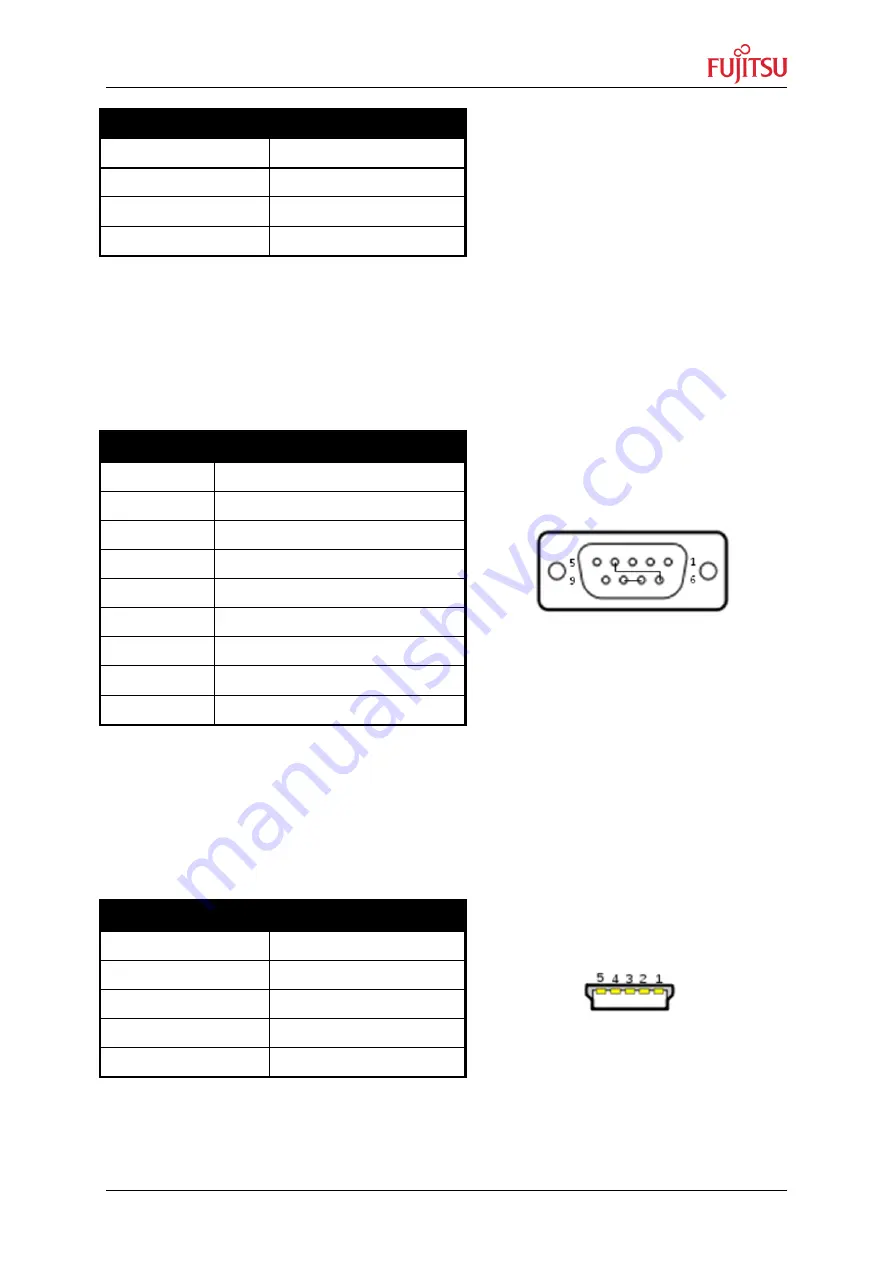
The connector of the UART
’A’ is a female 9-pin D-Sub connector. TXD is the transmit
output, RXD is the receive input.
Please use a 1:1 cable for PC connection.
X14 pin no.
Signal
1
DCD (input): 12V for LIN
2
TxD (output)
3
RxD (input)
4
DTR (input)
5
GND
6
DSR (output)
7
RTS (input)
8
CTS (output)
9
GND
Table 20: UART 'A' connector
5.9 USB
’A’ Connector (X16)
The conne
ctor of the UART’B’ is a mini USB connector. Via a USB-A to mini USB-B cable
the board can get connected to a PC.
X16 pin no.
Signal
1
VBUS
2
USBDM
3
USBDP
4
ID (n/c)
5
GND
Table 21: USB 'A' connector
Figure 6: UART'A' connector
Figure 7: USB 'A' connector


