


Chapter 6
Replacement of CPU/Memory Board Unit (CMU), CPU Module, and DIMM
6-33
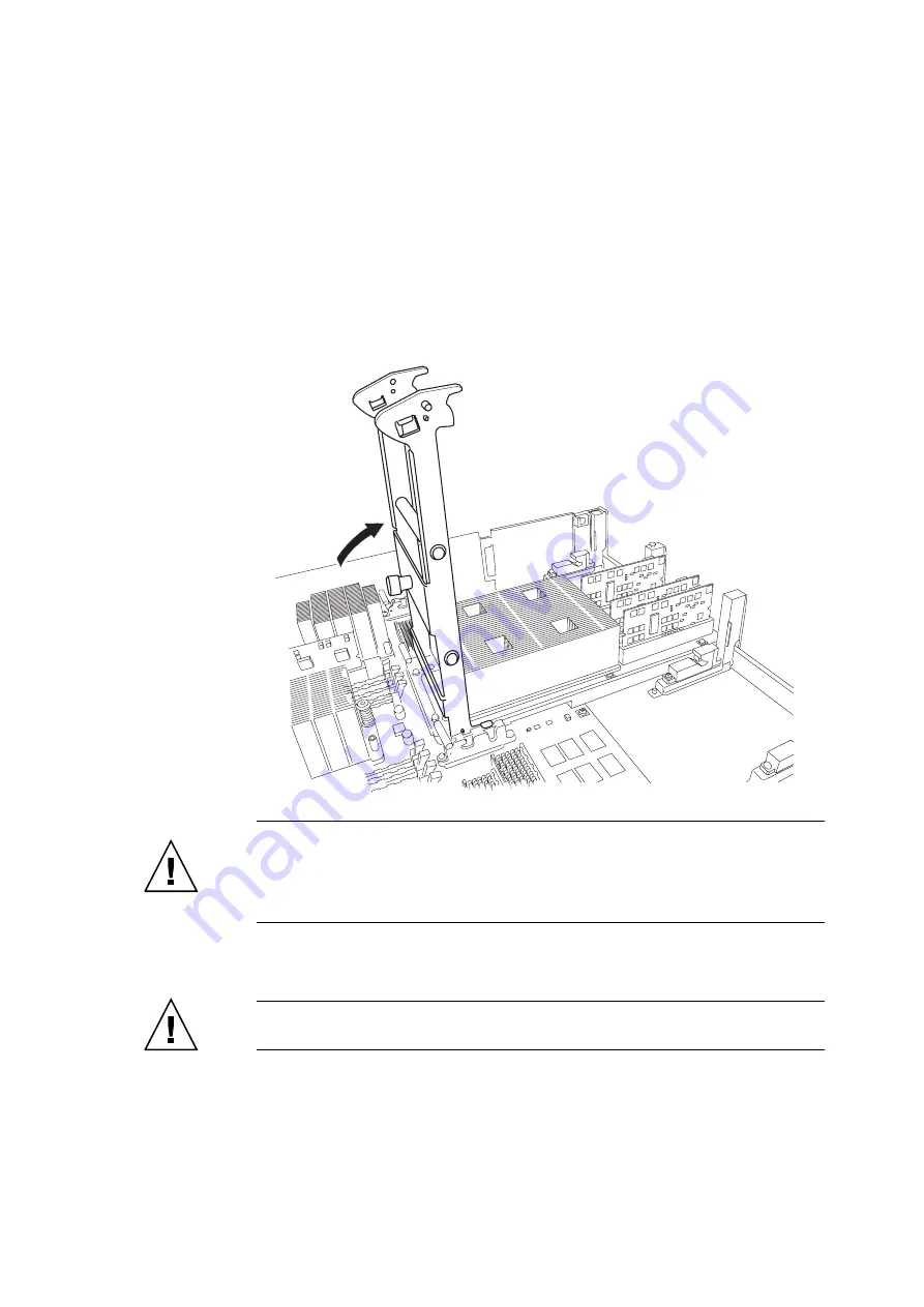
9. Raise the CPU Module insertion/extraction tool on the CPU Module side until the
tool is standing upright, perpendicular to the ground.
The CPU module and CMU connectors are coupled, and the new CPU module is
mounted.
FIGURE 6-25
Mounting the CPU Module
Caution –
Each CPU Module has two CMU guide locks. Perform the work in such a way
that both guide locks are correctly set. Raise the insertion/extraction tool until it touches the
stopper and is perpendicular to the ground. The connector is securely engaged when the
insertion/extraction tool is raised vertically and it comes into contact with the stopper. Do not
forcibly raise the insertion/extraction tool further.
10. Move the CPU module insertion/extraction tool in the opposite way of
remove the tool.
Caution –
After using the CPU module insertion/extraction tool, be sure to return it to the
storage location in the server.
Summary of Contents for SPARC Enterprise M8000
Page 4: ......
Page 15: ...Contents xv Index Index 1 ...
Page 16: ...xvi SPARC Enterprise M8000 M9000 Servers Service Manual October 2012 ...
Page 22: ......
Page 27: ...Chapter 1 Safety and Tools 1 5 M9000 Server Front View ...
Page 29: ...Chapter 1 Safety and Tools 1 7 Power Supply Unit PSU ...
Page 38: ...1 16 SPARC Enterprise M8000 M9000 Servers Service Manual October 2012 ...
Page 88: ...2 50 SPARC Enterprise M8000 M9000 Servers Service Manual October 2012 ...
Page 148: ......
Page 154: ...5 6 SPARC Enterprise M8000 M9000 Servers Service Manual October 2012 ...
Page 205: ...Chapter 7 I O Unit IOU Replacement 7 13 FIGURE 7 8 Removing the IOU Front of M9000 1 1 2 3 ...
Page 227: ...Chapter 8 FAN Unit Replacement 8 11 FIGURE 8 9 Removing the FAN Unit Rear of M8000 1 2 ...
Page 256: ...10 8 SPARC Enterprise M8000 M9000 Servers Service Manual October 2012 ...
Page 272: ...11 16 SPARC Enterprise M8000 M9000 Servers Service Manual October 2012 ...
Page 312: ...13 30 SPARC Enterprise M8000 M9000 Servers Service Manual October 2012 ...
Page 340: ...15 14 SPARC Enterprise M8000 M9000 Servers Service Manual October 2012 ...
Page 358: ...17 10 SPARC Enterprise M8000 M9000 Servers Service Manual October 2012 ...
Page 370: ...18 12 SPARC Enterprise M8000 M9000 Servers Service Manual October 2012 ...
Page 380: ...19 10 SPARC Enterprise M8000 M9000 Servers Service Manual October 2012 ...
Page 409: ...Chapter 20 Backplane Replacement 20 29 FIGURE 20 16 Removing the FANBP Rear of the M8000 ...
Page 422: ...21 10 SPARC Enterprise M8000 M9000 Servers Service Manual October 2012 ...
Page 439: ...Chapter 23 Switch Backplane Replacement 23 7 FIGURE 23 4 Removing the SWBP Rear of the M8000 ...
Page 442: ...23 10 SPARC Enterprise M8000 M9000 Servers Service Manual October 2012 ...
Page 460: ...24 18 SPARC Enterprise M8000 M9000 Servers Service Manual October 2012 ...
Page 484: ...25 24 SPARC Enterprise M8000 M9000 Servers Service Manual October 2012 ...
Page 494: ...A 10 SPARC Enterprise M8000 M9000 Servers Service Manual October 2012 ...
Page 544: ...C 4 SPARC Enterprise M8000 M9000 Servers Service Manual October 2012 ...
Page 552: ...D 8 SPARC Enterprise M8000 M9000 Servers Service Manual October 2012 ...


