13-4
SPARC Enterprise M8000/M9000 Servers Service Manual • October 2012
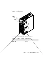
shows abbreviated name and numbers of PCI slots in an IOU.
For the following devices, replacement procedures have the same steps except that LEDs to
be checked, eject levers, and names used for status display are different.
■
PCI cassette (PCICS)
■
PCI card
■
IOU onboard device card (IOUA)
■
Link card
Note –
The steps of the replacement procedures for I/O boxes and link cards mounted in
external I/O expansion units, PCI cards, I/O boards, and power supply units are basically the
same as those described in this manual. For details, see the
External I/O Expansion Unit
Installation and Service Manual
.
The following explains the replacement procedure for a PCI card, which is a typical example.
13.2
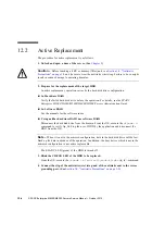
Active Replacement
The PHP function enables active replacement of PCI cassettes (PCICSs) and link card.
Active replacement cannot be performed for IOU onboard device cards (IOUAs).
The active replacement procedure is as follows.
1. Unlock and open a door of the server. (See
Caution –
Before touching a FRU or dummy (filler) unit, see
and be sure to wear the antistatic wrist strap. Failure to do so might
result in serious damage to operating domains.
TABLE 13-1
Abbreviated Name and Numbers of PCI Slots
Slot Name
Abbreviated Name and Numbers
PCI slot
PCI#0 to 7
Summary of Contents for SPARC Enterprise M8000
Page 4: ......
Page 15: ...Contents xv Index Index 1 ...
Page 16: ...xvi SPARC Enterprise M8000 M9000 Servers Service Manual October 2012 ...
Page 22: ......
Page 27: ...Chapter 1 Safety and Tools 1 5 M9000 Server Front View ...
Page 29: ...Chapter 1 Safety and Tools 1 7 Power Supply Unit PSU ...
Page 38: ...1 16 SPARC Enterprise M8000 M9000 Servers Service Manual October 2012 ...
Page 88: ...2 50 SPARC Enterprise M8000 M9000 Servers Service Manual October 2012 ...
Page 148: ......
Page 154: ...5 6 SPARC Enterprise M8000 M9000 Servers Service Manual October 2012 ...
Page 205: ...Chapter 7 I O Unit IOU Replacement 7 13 FIGURE 7 8 Removing the IOU Front of M9000 1 1 2 3 ...
Page 227: ...Chapter 8 FAN Unit Replacement 8 11 FIGURE 8 9 Removing the FAN Unit Rear of M8000 1 2 ...
Page 256: ...10 8 SPARC Enterprise M8000 M9000 Servers Service Manual October 2012 ...
Page 272: ...11 16 SPARC Enterprise M8000 M9000 Servers Service Manual October 2012 ...
Page 312: ...13 30 SPARC Enterprise M8000 M9000 Servers Service Manual October 2012 ...
Page 340: ...15 14 SPARC Enterprise M8000 M9000 Servers Service Manual October 2012 ...
Page 358: ...17 10 SPARC Enterprise M8000 M9000 Servers Service Manual October 2012 ...
Page 370: ...18 12 SPARC Enterprise M8000 M9000 Servers Service Manual October 2012 ...
Page 380: ...19 10 SPARC Enterprise M8000 M9000 Servers Service Manual October 2012 ...
Page 409: ...Chapter 20 Backplane Replacement 20 29 FIGURE 20 16 Removing the FANBP Rear of the M8000 ...
Page 422: ...21 10 SPARC Enterprise M8000 M9000 Servers Service Manual October 2012 ...
Page 439: ...Chapter 23 Switch Backplane Replacement 23 7 FIGURE 23 4 Removing the SWBP Rear of the M8000 ...
Page 442: ...23 10 SPARC Enterprise M8000 M9000 Servers Service Manual October 2012 ...
Page 460: ...24 18 SPARC Enterprise M8000 M9000 Servers Service Manual October 2012 ...
Page 484: ...25 24 SPARC Enterprise M8000 M9000 Servers Service Manual October 2012 ...
Page 494: ...A 10 SPARC Enterprise M8000 M9000 Servers Service Manual October 2012 ...
Page 544: ...C 4 SPARC Enterprise M8000 M9000 Servers Service Manual October 2012 ...
Page 552: ...D 8 SPARC Enterprise M8000 M9000 Servers Service Manual October 2012 ...


