Chapter 9
Power Supply Unit (PSU) Replacement
9-13
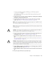
9. Go back to the terminal that is connected to XSCF, and perform the input operation
according to the instructions on the maintenance menu that is displayed after the
replacement.
a. Perform operation according to instructions of messages. When the display of the
maintenance menu returns to the initial page, the operation is completed.
b. Exit the maintenance menu.
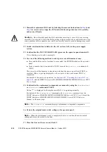
10. Confirm that the replacement components are normal by using the
showhardconf
or
showstatus
command of XSCF.
Unless "*" is displayed for the replacement PSU, it is operating normally.
For details of the
showhardconf
command and
showstatus
command, see the
SPARC Enterprise M3000/M4000/M5000/M8000/M9000 Servers XSCF User’s Guide
, the
SPARC Enterprise M3000/M4000/M5000/M8000/M9000 Servers XSCF Reference
Manual
, or the man page.
Note –
The
showstatus
command displays information on degraded components.
11. Close the door on the server, and lock it.
9.3
Cold Replacement
In cold replacement, none of the replacement work is performed with the maintenance menu
from a terminal connected to XSCF.
The procedure is as follows.
1. Unlock and open a door of the server. (See
Caution –
Before touching a FRU or dummy (filler) unit, see
and be sure to wear the antistatic wrist strap. Failure to do so might
result in serious damage to operating domains.
2. Change the mode switch setting on the operator panel from Locked to Service.
Note –
When the maintenance work is completed, be sure to confirm the mode switch
setting and return the switch to Locked.
3. Use one of the following methods to stop (power off) all domains at once.
Summary of Contents for SPARC Enterprise M8000
Page 4: ......
Page 15: ...Contents xv Index Index 1 ...
Page 16: ...xvi SPARC Enterprise M8000 M9000 Servers Service Manual October 2012 ...
Page 22: ......
Page 27: ...Chapter 1 Safety and Tools 1 5 M9000 Server Front View ...
Page 29: ...Chapter 1 Safety and Tools 1 7 Power Supply Unit PSU ...
Page 38: ...1 16 SPARC Enterprise M8000 M9000 Servers Service Manual October 2012 ...
Page 88: ...2 50 SPARC Enterprise M8000 M9000 Servers Service Manual October 2012 ...
Page 148: ......
Page 154: ...5 6 SPARC Enterprise M8000 M9000 Servers Service Manual October 2012 ...
Page 205: ...Chapter 7 I O Unit IOU Replacement 7 13 FIGURE 7 8 Removing the IOU Front of M9000 1 1 2 3 ...
Page 227: ...Chapter 8 FAN Unit Replacement 8 11 FIGURE 8 9 Removing the FAN Unit Rear of M8000 1 2 ...
Page 256: ...10 8 SPARC Enterprise M8000 M9000 Servers Service Manual October 2012 ...
Page 272: ...11 16 SPARC Enterprise M8000 M9000 Servers Service Manual October 2012 ...
Page 312: ...13 30 SPARC Enterprise M8000 M9000 Servers Service Manual October 2012 ...
Page 340: ...15 14 SPARC Enterprise M8000 M9000 Servers Service Manual October 2012 ...
Page 358: ...17 10 SPARC Enterprise M8000 M9000 Servers Service Manual October 2012 ...
Page 370: ...18 12 SPARC Enterprise M8000 M9000 Servers Service Manual October 2012 ...
Page 380: ...19 10 SPARC Enterprise M8000 M9000 Servers Service Manual October 2012 ...
Page 409: ...Chapter 20 Backplane Replacement 20 29 FIGURE 20 16 Removing the FANBP Rear of the M8000 ...
Page 422: ...21 10 SPARC Enterprise M8000 M9000 Servers Service Manual October 2012 ...
Page 439: ...Chapter 23 Switch Backplane Replacement 23 7 FIGURE 23 4 Removing the SWBP Rear of the M8000 ...
Page 442: ...23 10 SPARC Enterprise M8000 M9000 Servers Service Manual October 2012 ...
Page 460: ...24 18 SPARC Enterprise M8000 M9000 Servers Service Manual October 2012 ...
Page 484: ...25 24 SPARC Enterprise M8000 M9000 Servers Service Manual October 2012 ...
Page 494: ...A 10 SPARC Enterprise M8000 M9000 Servers Service Manual October 2012 ...
Page 544: ...C 4 SPARC Enterprise M8000 M9000 Servers Service Manual October 2012 ...
Page 552: ...D 8 SPARC Enterprise M8000 M9000 Servers Service Manual October 2012 ...

