Chapter 24
Addition and Deletion of a RDPF Option, Power Cabinet, and M9000 Expansion Cabinet
24-13
■
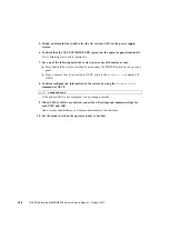
From a console that is connected to XSCF, execute the
poweron -a
command of
XSCF.
The power to all the domains is turned on, and then the power-on self test (POST) is
executed. When
ok
prompt displayed on the console of relevant domain, POST is
completed.
For details of the power-on operation, see
Section 4.4.2, “Powering the Server On” on
, and the
SPARC Enterprise M3000/M4000/M5000/M8000/M9000 Servers XSCF
User’s Guide
.
14. Confirm that the replacement components are normal by using the
showhardconf
or
showstatus
command of XSCF.
Unless "*" is displayed for the replacement RDPF, it is operating normally.
For details of the
showhardconf
command and
showstatus
command, see the
SPARC Enterprise M3000/M4000/M5000/M8000/M9000 Servers XSCF User’s Guide
, the
SPARC Enterprise M3000/M4000/M5000/M8000/M9000 Servers XSCF Reference
Manual
, or the man page.
Note –
The
showstatus
command displays information on degraded components.
15. Restore the original mode switch setting on the operator panel.
Note –
When the maintenance work is completed, be sure to confirm the mode switch
setting and return the switch to Locked.
16. Close the door on the server, and lock it.
24.1.2.2
Deletion
Follow the addition instructions in reverse order.
24.2
Addition and Deletion of Power Cabinet
The three procedures listed below can be used. Regardless of the procedure used, see the
power cabinet installation procedure explained in the
SPARC Enterprise M8000/M9000
Servers Installation Guide
.
■
Adding or deleting a power cabinet for the M8000 server with three-phase dual power
feed configured
Summary of Contents for SPARC Enterprise M8000
Page 4: ......
Page 15: ...Contents xv Index Index 1 ...
Page 16: ...xvi SPARC Enterprise M8000 M9000 Servers Service Manual October 2012 ...
Page 22: ......
Page 27: ...Chapter 1 Safety and Tools 1 5 M9000 Server Front View ...
Page 29: ...Chapter 1 Safety and Tools 1 7 Power Supply Unit PSU ...
Page 38: ...1 16 SPARC Enterprise M8000 M9000 Servers Service Manual October 2012 ...
Page 88: ...2 50 SPARC Enterprise M8000 M9000 Servers Service Manual October 2012 ...
Page 148: ......
Page 154: ...5 6 SPARC Enterprise M8000 M9000 Servers Service Manual October 2012 ...
Page 205: ...Chapter 7 I O Unit IOU Replacement 7 13 FIGURE 7 8 Removing the IOU Front of M9000 1 1 2 3 ...
Page 227: ...Chapter 8 FAN Unit Replacement 8 11 FIGURE 8 9 Removing the FAN Unit Rear of M8000 1 2 ...
Page 256: ...10 8 SPARC Enterprise M8000 M9000 Servers Service Manual October 2012 ...
Page 272: ...11 16 SPARC Enterprise M8000 M9000 Servers Service Manual October 2012 ...
Page 312: ...13 30 SPARC Enterprise M8000 M9000 Servers Service Manual October 2012 ...
Page 340: ...15 14 SPARC Enterprise M8000 M9000 Servers Service Manual October 2012 ...
Page 358: ...17 10 SPARC Enterprise M8000 M9000 Servers Service Manual October 2012 ...
Page 370: ...18 12 SPARC Enterprise M8000 M9000 Servers Service Manual October 2012 ...
Page 380: ...19 10 SPARC Enterprise M8000 M9000 Servers Service Manual October 2012 ...
Page 409: ...Chapter 20 Backplane Replacement 20 29 FIGURE 20 16 Removing the FANBP Rear of the M8000 ...
Page 422: ...21 10 SPARC Enterprise M8000 M9000 Servers Service Manual October 2012 ...
Page 439: ...Chapter 23 Switch Backplane Replacement 23 7 FIGURE 23 4 Removing the SWBP Rear of the M8000 ...
Page 442: ...23 10 SPARC Enterprise M8000 M9000 Servers Service Manual October 2012 ...
Page 460: ...24 18 SPARC Enterprise M8000 M9000 Servers Service Manual October 2012 ...
Page 484: ...25 24 SPARC Enterprise M8000 M9000 Servers Service Manual October 2012 ...
Page 494: ...A 10 SPARC Enterprise M8000 M9000 Servers Service Manual October 2012 ...
Page 544: ...C 4 SPARC Enterprise M8000 M9000 Servers Service Manual October 2012 ...
Page 552: ...D 8 SPARC Enterprise M8000 M9000 Servers Service Manual October 2012 ...


