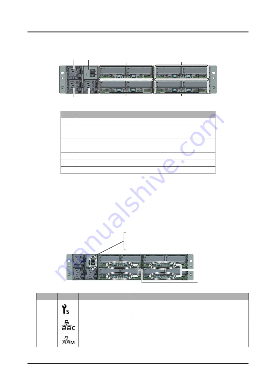
(7)
(8)
(4)
(6)
(5)
(2)
(3)
(1)
Location
Component
(1)
CMU#00
(2)
CMU#01
(3)
CMU#02
(4)
CMU#03
(5)
PSU#00
(6)
PSU#01
(7)
PSU#02
(8)
BMCIF#00
Top
Bottom
(3)
(3)
(1)
(2)
Location
Display
Name
Description
(1)
Maintenance
port
Used
to
connect
a
maintenance
work
terminal
when
performing
maintenance
work
(2)
Control
port
Connected
to
the
BMC
and
used
for
hardware
status
monitoring,
failure
notification,
and
power
control
(3)
Management
port
Used
to
connect
nodes
Figure
A.3
Rear
Configuration
of
the
FX700
Main
Unit
A.1.3
LANs
of
the
FX700
Main
Unit
This
section
shows
the
locations
of
the
BMC
maintenance
port,
BMC
control
port,
and
node
management
ports.
Figure
A.4
Rear
Locations
for
the
LANs
of
the
FX700
Main
Unit
Appendix
A
External
Views
of
the
Device
C120-0090-04EN
A.1
External
Views
of
the
Device
74
Summary of Contents for Supercomputer PRIMEHPC FX700
Page 105: ......


