En-2
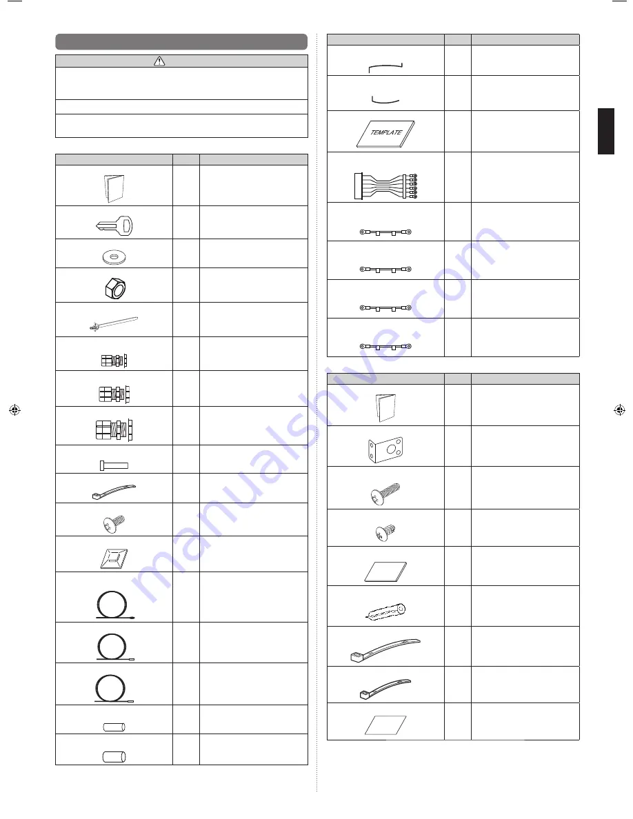
2.3. Accessories
WARNING
For installation purposes, be sure to use the parts supplied by the manufacturer or
other prescribed parts. The use of non-prescribed parts can cause serious accidents
such as the unit falling, water leakage, electric shock, or
fi
re.
The following installation parts are furnished. Use them as required.
Keep the Installation Manual in a safe place and do not discard any other accessories
until the installation work has been completed.
(1) Control unit Accessories
Name and Shape
Q’ty
Application
Installation Manual
1
(This book)
Key
2
For the door of control unit
Sealing washer
3
For mounting the control unit to the
wall Waterproof specifications
Nuts (M8)
3
For mounting the control unit to the
wall
Cable ties (with stopper)
19
For securing the cables
Cable gland (M10)
4
For cable holes
Cable gland (M16)
5
For cable holes
Cable gland (M20)
1
For cable holes
Blind bar
5
For mounting when not passing the
cable through the cable gland
Cable tie
3
For securing the optional remote
controller cable
Screw (M4×L6 mm)
3
For mounting the optional remote
controller
Cable tie mount
2
For securing the optional remote
controller cable
Thermistor
(Inlet air and Outlet air)
2
For measuring the room
temperature
Thermistor (Label: GAS)
1
For measuring the gas pipe
temperature
(For gas pipes)
Thermistor (Label: LIQ)
1
For measuring the liquid pipe
temperature
(For liquid pipes)
Thermistor holder pipe
(Small)
1
For mounting the thermistor
Thermistor holder pipe
(Large)
1
For mounting the thermistor
Name and Shape
Q’ty
Application
Thermistor spring (For small thermistor
holder pipe)
1
For mounting the thermistor
Thermistor spring (For large thermistor
holder pipe)
1
For mounting the thermistor
Template
1
For installing the control unit
Connection cable 1
[Label : 32,33,35,37,39,41]
1
For external output
Connection cable 2
[Label : 32,34]
1
For external output
Connection cable 3
[Label : 34,36]
1
For external output
Connection cable 4
[Label : 36,38]
1
For external output
Connection cable 5
[Label : 38,40]
1
For external output
(2) EEV unit Accessories
Name and Shape
Q’ty
Application
Installation Manual
1
―
Secure fitting
4
For mounting the EEV unit to the
wall, or stacking multiple EEV units
Tapping Screw L (M4×L16)
8
For mounting the EEV unit to the
wall
Tapping Screw S (M4×L10)
8
For stacking multiple EEV unit
Rubber sheet
2
For mounting pipe joints
Pipe heat insulations
2
For mounting pipe joints
cable tie (Large)
4
For securing heat insulations
cable tie (Medium)
1
For securing cables
Seal
2
For pasting unused piping holes
9381279005_IM.indb 2
9381279005_IM.indb 2
6/30/2014 11:31:17 AM
6/30/2014 11:31:17 AM


