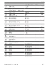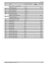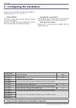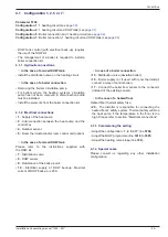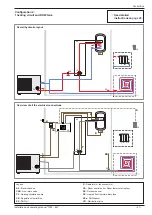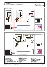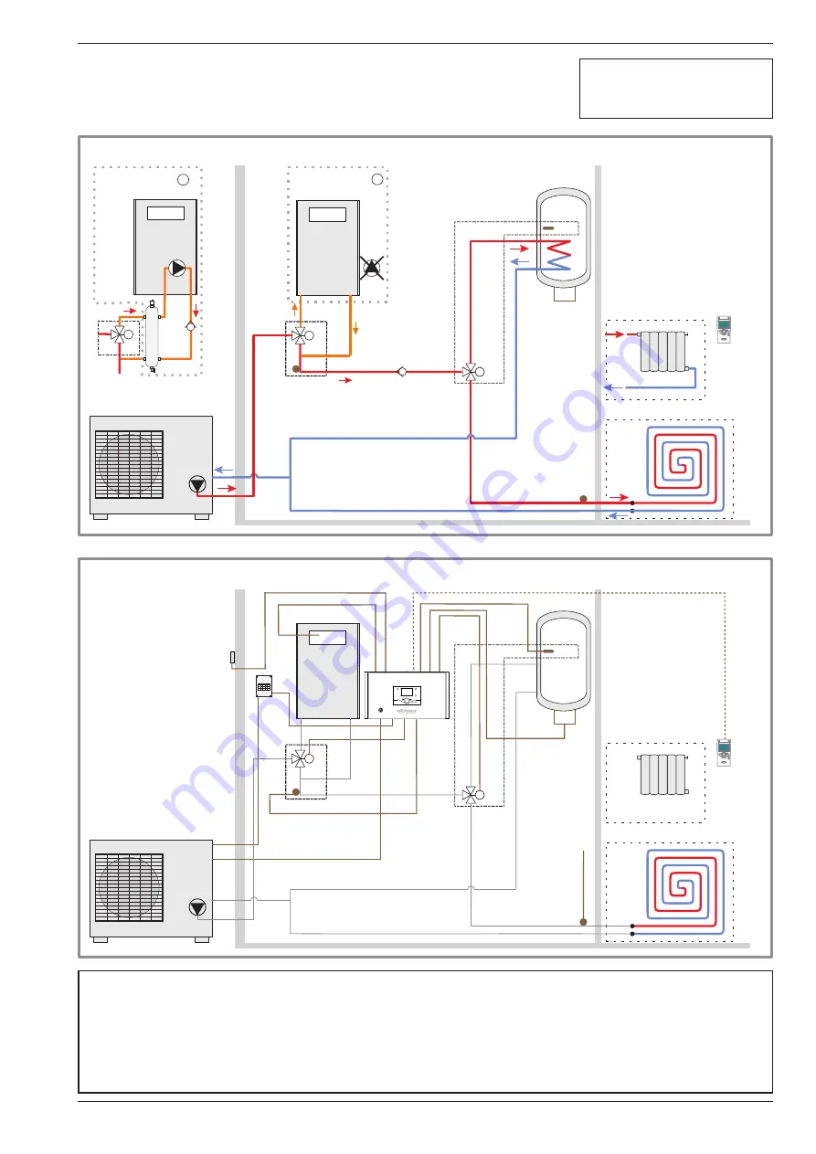
Configuration 7 :
Boiler connection, 1 heating circuit and DHW tank
M
VD
KS
SSa
AE
R
SP
CA
SDR
M
VDI
CC
SE
4
10
16
15
17
2
1
20
9
7
8
5
TA
CR
Overview of all the electrical connections
M
VD
KS
SSa
AE
R
SP
CA
SDR
M
VDI
CC
M
VDI
CCI
BD
CAT
D
A
CCI
CAT
Overall hydraulic layout
Legend
AE
- Electric back-up
BD
- Disconnection bottle
CAT
- Anti-gravity feed valve
CCI
- Heating system circulation pump built into the boiler
CC
- Heating circulation pump
CR
- Regulation Control Box
R
- Radiators (or fan convectors)
CA -
Room control unit
or Room thermostat (option)
KS
- DHW kit
SE
- Outdoor sensor
SDR
- Boiler connection valve flow sensor
SSa
- DHW sensor
SP
- Heated floor thermal safety fuse
TA -
Boiler supply of boiler unit
VD
- Distribution valve
VDI
- Distribution valve (deviation boiler)
Ex : boiler unit
Ex : boiler unit
"
See detailed
instructions on
Installation and operating manual "1395 - EN"
- 33 -
Control Box


