XG0440DC/XG0440DCR Hardware Guide
Chapter 1 Getting Started
Items in the Package, Descriptions and Functions
22
1.1.3
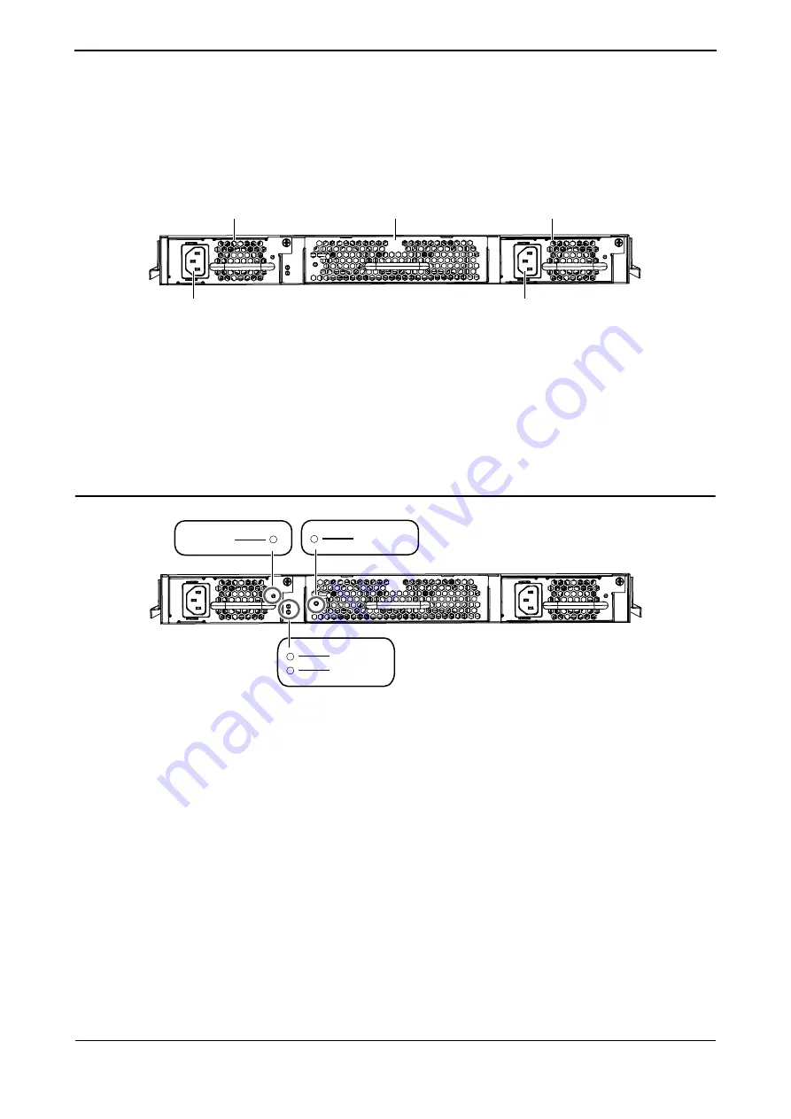
Switch Power Inlet Side
The XG0440DC is used as an example.
The front and back direction of the rack mounting brackets attached to the side of the switch is reversed for the XG0440DC
and XG0440DCR.
•
Power Inlet
Plug the attached Power Cable in the package.
•
PSU Slots
Power Supply Units are interchangeable between slots. The Power Supply Units are hot-
swappable.
•
Power Supply Unit
This switch is installed with two PSUs.
•
Fan Unit
This switch is provided with one Fan Unit.
LED Details
•
POWER LED
Lights to indicate the status of the PSU.
•
STATUS LED
Lights to show the status of the Fan Unit.
•
READY LED
Indicates the operational state of the switch.
•
CHECK LED
Lights orange when the switch detected an abnormal operating condition. This may
indicate that the switch has failed. Consult with your Fujitsu or Fujitsu's certified
support engineer immediately to correct this condition.
Fan
Unit
Power
Inlet
Power
Inlet
PSU
Slots
PSU1
Power
Supply
Unit
PSU
Slots
PSU2
Power
Supply
Unit
POWER
READY
CHECK
STATUS


